04 INSTALLATION AND OPERATING INSTRUCTIONS PRECISION
®
FILTER CLEANING SYSTEM CONTROLS
Your system may have some or all of these components. Note that terminal headers are supplied for all push-in contacts.
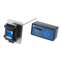
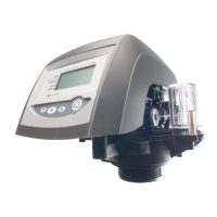
Figure 1:
P1 Interface and Controller, Top View
4
5
3
22
6
1278
9
23
4
5
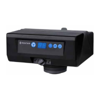
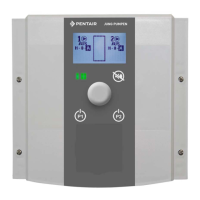
Figure 2: Controller, Front View
71211 2010
D IRTY
C LEAN
21
Note: Controller assemblies in
Figures 1 and 2 include (left to right)
P-CTX, P-MOD and P2 interface, all
mounted on the AC/AC baseboard.
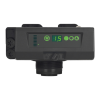
Figure 3:
PS-C, DC Output Compact Terminal Expansion Card
17
16
18
1514
13
IDENTIFYING THE PARTS
 Loading...