S
sancheztonyAug 16, 2025
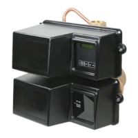
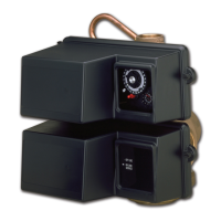
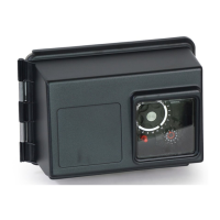
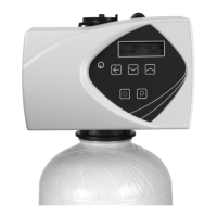
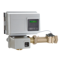
What to do if my Pentair FLECK 3150 NXT water softener fails to regenerate?
- NNathan HartAug 16, 2025
If your Pentair Control Unit water softener isn't regenerating, it could be due to a few reasons. First, ensure the unit has continuous electrical service by checking the fuse, plug, and switch. If the power was interrupted, reset the time of day. If the timer is defective, consider replacing the controller.