Installer Manual Fleck 3150 - NXT - Installation
Ref. MKT-IM-010 / B - 28.05.2018 37 / 122
• soldering near the drain line should be done before connecting the drain line to the valve.
Excessive heat will cause interior damage to the valve;
• do not use lead-based solder for sweat solder connections;
• the riser tube should be cut 6 to 19 mm below the top of the tank. Slightly bevel the ridge in order
to avoid deterioration of the seal whilst fitting the valve;
• the drain line must be a minimum of 25.4 mm (1") in diameter;
• do not support the weight of the system on the valve fittings, plumbing, or the bypass;
• it is not recommended to use sealants on the threads. Use PTFE (plumber’s tape) on the threads
of the drain elbow, and other NPT/BSP threads;
• the installation of a pre filter is always recommended (100μ nominal);
• valve inlet/outlet must be connected to main piping via flexible.
5.4. Integration constraints
Location of a water treatment system is important. The following conditions are required:
• flat and firm level platform or floor;
• room to access equipment for maintenance and adding brine (salt) to tank;
• constant electrical supply to operate the controller;
• total minimum pipe run to water heater of 3 m (10 ft) to prevent backup of HW into system;
• always install check valve before water heater to protect the softener from HW return;
• local drain for discharge as close as possible;
• water line connections with shut off or bypass valves;
• must meet any local and state codes for site of installation;
• valve is designed for minor plumbing misalignments. Do not support weight of system on the
plumbing;
• be sure all soldered pipes are fully cooled before attaching plastic valve to the plumbing.
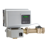
5.5. Valve connection to piping
The connections should be hand tightened using PTFE (plumber’s tape) on the threads if using the
threaded connection type.
In case of heat welding (metal type connection), the connections should not be made to the valve when
soldering.
Note
See chapter 3.3. Components description and location, page 17 to identify the connections.
When pressurized, any composite tank will expand both vertically and circumferential. In order to
compensate the vertical expansion, the piping connections to the valve must be flexible enough to
avoid overstress on the valve and tank.

 Loading...