- 3 -
Belt/Pulley Drive Installation (cont’d.)
To figure proper diameter of pump pulley, multiply motor/
engine rpm by diameter of the motor/engine pulley and
divide that figure by desired pump speed.
Pump = Motor RPM x Motor Pulley Size
Pulley Size Desired Pump Speed
Refer to pump performance charts to determine desired
speed to obtain desired maximum flow.
IMPORTANT: Note that shaft rotation is counter-
clockwise as viewed from the shaft - opposite from
most standard centrifugals. Be sure to drive pump
in proper direction.
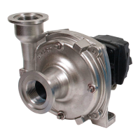
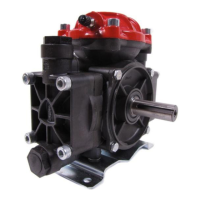
Series 9200 Pedestal-Mounted Centrifugal
Pumps
To install couplings, slide coupling ends onto motor
or engine and pump shafts as far as possible. Mount
engine/motor and pump on base. Shim up pump or
power to align shafts. Leave enough room between
shaft ends to install center disc. When aligned, slide
ends over disc. Select couplings rated twice required
horsepower when using motor; three times when using
gas engine.
Refer to your pump parts breakdown.
1. Lubricate the seal cavity in the flange with WD-40,
LPS or equivalent.
Be extremely careful with the new seal. Take
special care not to scratch the lapped sealing
faces of the rotary seal and stationary seat.
2. Install the stationary portion of the mechanical seal
by pushing it into the bore of the flange with the
ceramic side out.
Important: Make sure the seal “cavity” is clean
and lubricated. Never run the sealing faces dry.
3. To seat the seal in the seal cavity, use a piece of
3/4” PVC pipe (1” for 1551) 4” to 6” in length. Press
seal in firmly and squarely.
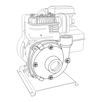
4. Install slinger ring onto gas engine shaft.
5. Install flange onto the gas engine. Make sure the
flange bore fits into the bore on the engine.
See Fig. 4.
6. Insert four bolts and four seals (four bolts only for
1551) through the flange and into the gas engine.
Tighten to 80-100 inch pounds of torque.
7. To install the rotary portion of the mechanical seal,
place it over the shaft with the carbon side facing in,
and press until it bottoms out against the stationary
seal portion.
Important: Use care in installing the seal on the
shaft. The seal can be damaged by threads on
the engine shaft.
8. Install the gasket over the shaft against the rotary
portion of the seal.
9. Install the impeller onto the shaft, and hand tighten
until it is secure.
10. Install the o-ring on the mounting flange.
11. Place the pump casing on the mounting flange;
insert the bolts and tighten evenly.
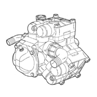
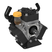
Direct Drive - Flexible Coupling Installation
Direct Drive Gas Engine Installation for Models 1538 and 1551
Push the belt
midway between
the pulleys, check
the deflection (d)
and adjust:
d = 0.016 X L
NOTE: Direction
of shaft rotation, as
viewed from the shaft
side, is counterclockwise
for Series 9200 and
clockwise for 9500P.
9200P is shown.
Figure 2
Figure 3
Figure 4
 Loading...