- 4 -
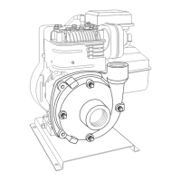
Direct Drive - Flange Mount Installation
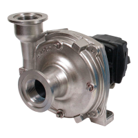
GAS ENGINE MOUNT — Model 9513P fits most 5 hp
gas engines with flange mount and 3/4” shaft.
To install pump onto gas engine, first apply anti-seize
compound to gas engine shaft and to inside of pump
hollow shaft. Insert key into engine shaft. Next, slide
pump onto engine shaft and secure with four hex head
bolts. NOTE: Do not force pump onto shaft. Tighten set
screws on pump shaft through slots in flange. Check to
make sure pump rotates freely by slowly turning over the
gas engine.
Operation and Maintenance
IMPORTANT: ENGAGE PTO CLUTCH SLOWLY
AND SMOOTHLY. AVOID SUDDEN STARTS AND
FAST CLUTCHING THAT CAN DAMAGE THE DRIVE
SECTION OF THE PUMPS.
Controlling the Flow
Two flow control valves are used - one in the agitation
line and one in the line leading to the boom or spray
gun. This permits controlling agitation flow independently
of nozzle flow.
To Adjust For Spraying
To adjust sprayer (regardless of power source - PTO,
belt or pulley), follow these steps:
1. Prime pump with all valves open.
2. Close control valve and agitation line valve; open
boom shut-off valve.
3. With pump running, open the control valve until
pressure gauge indicates desired spraying pressure.
4. Open the agitation line valve until sufficient agitation
is observed. Then, if spraying pressure drops, readjust
the control valve to restore desired pressure.
5. Make sure flow is uniform from all nozzles.
After spraying adjustments are made, it is only
necessary to close boom shut-off valve to discontinue
spraying. On belt-drive models, check belt tension daily
or before each use.
Flush Pump After Use
One of the most common causes for faulty pump
performance is “gumming” or corrosion inside the
pump. Flush the pump and entire system with a solution
that will chemically neutralize the liquid pumped. Mix
according to manufacturer’s directions. This will dissolve
most residue remaining in the pump, leaving the inside
of the pump clean for the next use.
To Prevent Corrosion
After cleaning the pump as directed above, flush it with
a permanent-type automobile antifreeze (Prestone,
Zerex, etc.) containing a rust inhibitor. Use a 50%
solution - that is, half antifreeze and half water. Plug the
ports to keep out air during storage. For short periods of
idleness, non-corrosive liquids may be left in the pump,
BUT AIR MUST BE KEPT OUT. Plug ports or seal port
connections.
Troubleshooting
System Probable Cause(s) Corrective Action(s)
Low Discharge Pump not primed. Remove topmost vent plug from face of pump and run pump to expel trapped air
(See Installation Instructions). Recommend vent line be used (KIT#3430-0456).
Air leaks in suction line. Check and reseal inlet fittings.
Blocked or clogged
line strainer or impeller. Inspect strainer and impeller to clear any debris or obstruction.
Undersize suction line or
collapsed hose. Suction line should be the same diameter as inlet port of pump or larger.
Eye of impeller rubbing Remove volute (front cover) and inspect the impeller. If wear detected, sand
on volute. the impeller eye O.D. with emery cloth.
Liquid leaking Worn seal. Replace seal.
out weep port
Figure 5
 Loading...