and achieve the best filtration. Line strainers can also be
installed in the tank fill line to filter liquid as it is loaded into
the tank as well as in the boom lines to further filter the
solution prior to the spray tips. Tank baskets can also be
used to filter material added through the tank lid.
Agitation
The centrifugal pump control contains a manual agitation
control valve that can be adjusted to provide the right
amount of flow to the jet agitators in the tank to ensure
proper mixing within the tank.
Flowmeter
To eliminate the mechanical problems of a turbine flowmeter,
we recommend that an electromagnetic flowmeter be used.
These flowmeters have no moving parts to wear out and will
provide a more consistent and accurate flow reading. They
can be input into just about any electronic rate controller or
switch box.
Boom Section Valves
For rapid response and reliability, we recommend electric
plunger valves be used for boom control. The valves should
be sized accordingly to minimize the pressure drop and
maximize the flow rate. The boom tubing or hose should
be sized accordingly to ensure that a pressure drop in the
lines does not occur, causing inconsistent pressures at the
nozzles.
Nozzle Bodies
Nozzle bodies with shut-off check valves are recommended
to eliminate dripping from the spray tips when the boom
valves are shut down.
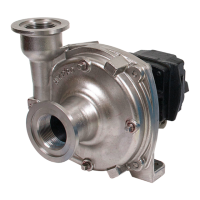
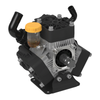
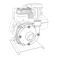
Hooking Up the Hydraulic Motor to the
Tractor Hydraulic System
Hypro Series 9300HMC hydraulic motor-driven pumps can
be mounted on either the tractor or sprayer. When hooking
up, make sure that no dirt or liquid gets into the hydraulic
motor. Keep all hydraulic connections clean. Be sure
to connect the hydraulic motor into the system correctly by
putting the pressure line to the Pressure Port Adapter and
return line to the Tank Port Adapter. The adapters on the
hydraulic motor are sized to accommodate 1/2” NPT fittings
on the pressure port and 3/4” NPT on the tank port. For
maximum performance, the hydraulic lines should also be at
least 1/2” [12.7 mm] in size for the pressure line and 3/4”
[19.05 mm] for the tank line.
The tank (OUT) port adapter with a built-in check valve
assembly will guard against reverse operation — allowing you
to reverse oil flow to operate other equipment. This adapter
must not be removed. On HM2C and HM4C model pumps,
the pressure (IN) port adapter is a two-piece assembly
consisting of an open (unrestricted) adapter with three orifices
packed loose with the pump. (See the Operations Section.)
When using the HM2C or HM4C unit on any flow- compensated
(load sensing) closed center system, or any small open center
system with a maximum flow of 8 gpm [30.28 lpm] for HM2C
or 10 gpm [37.85 lpm] for HM4C, the metering orifice should
be removed from the pressure port adapter. When using these
units on flow-compensated systems, connect to the motor
priority circuit if your tractor has one.
Standard spool valves, which are found on all tractor
hydraulic systems, may cause potentially damaging high
peak pressures in the hydraulic system when closed because
of abrupt shut-off of oil flow in both the supply and return
lines. When shutting off the pump, move the selector to the
FLOAT position to allow the centrifugal pump to come to a
stop gradually.
For further information
regarding Hypro products,
contact your local dealer or
Hypro directly at
www.hypropumps.com or by
calling 1-800-424-9776.
-6-
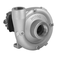
Open Center Systems— All Models
Adjusting Centrifugal Pump Output
HM1C, HM3C & HM5C motors have bypass screw fully
closed from the factory. HM2C & HM4C motors have bypass
screw set at 1-1/2 turns from fully closed from the factory.
1. Open the bypass adjustment screw 2-1/2 turns from fully
closed. Turn the bypass screw in to achieve the flow for
the desired gpm and psi.
2. Start the tractor. Leave the directional valve in the
neutral position and allow hydraulic oil to circulate for
approximately 10 to 15 minutes or until adequately
warmed.
3. Prime the centrifugal pump with all valves open (See
the Installation Instructions and System Configuration
Diagram).
4. Close the agitation line valve and keep the control
valve and the boom shut-off valve open. Note the spray
pressure.
5. Open the agitation line valve until you have desired
circulation in the tank. Recheck the spray pressure. If it
is too low, close down the agitation line valve until the
desired spray pressure is reached. If the spray pressure
is too high, throttle the centrifugal pump by closing down
the control valve.
Operation
Plumbing Installation
L-1526 (12/12, Rev. B)
 Loading...