4
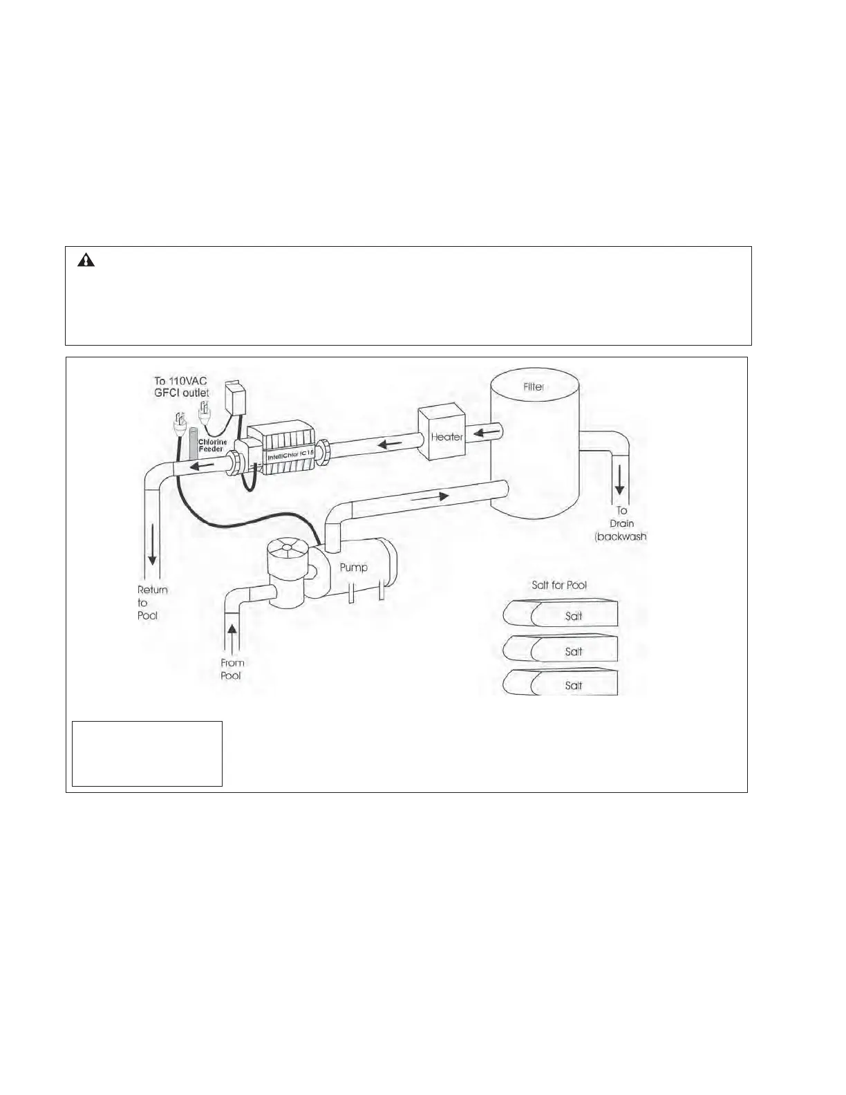
System Schematic Diagram
The following schematic diagram shows a typical IntelliChlor
®
SCG system installation.
Note: This schematic diagram is not drawn to scale. Refer to the relevant portions of this Installation
and User’s Guide for information regarding proper placement and spacing of all equipment depicted in
this diagram.
Install Chlorine/Bromine Feeders after the IntelliChlor SCG Cell
CAUTION - To avoid permanent damage to the IntelliChlor cell, automatic in-line chlorine/bromine feeders
(such as Pentair Water Pool and Spa
®
Rainbow models) MUST be installedAFTER the IntelliChlor cell as
shown below. When using the IntelliChlor with an in-floor cleaner pressure system, it is recommended that a
separate return line be used for the cleaner to reduce the increased water pressure stress on the IntelliChlor
cell.
Note: For best flow
sensing, provide at least
12"-18" of straight pipe in
front of the cell inlet.
NOT TO SCALE
IntelliChlor Salt Chlorine Generator Installation and User’s Guide

 Loading...