21
INTELLIFLO
®
Variable Speed Pump Installation and User’s GuideINTELLIFLO
®
Variable Speed Pump Installation and User’s Guide
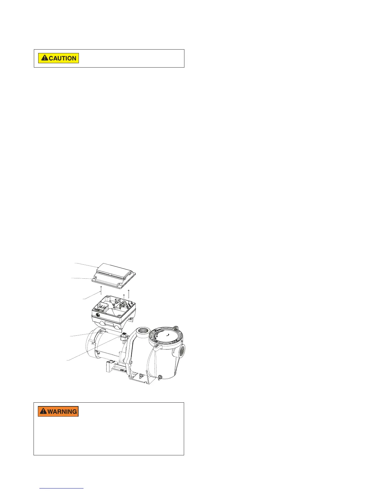
Drive Assembly Removal and
Installation, (continued)
To install the drive assembly onto the motor
assembly:
1. Be sure all electrical breakers and switches are turned
off before installing the drive.
2. Be sure that the gasket between the drive and motor
is in place. It is critical in keeping moisture out of the
drive and motor. Replace the gasket if damaged. Do
not reassemble with a damaged or missing gasket.
3. Verify that the three (3) orange motor post caps are
in position before placing the drive on the motor
assembly.
4. Align the drive assembly with the motor adapter and
seat the drive on the motor assembly.
5. Secure and tighten the drive assembly with the three
(3) Phillips head screws.
6. Plug the keypad cover back into the drive.
7. Place the keypad cover in the desired orientation
on the drive and reattach the four (4) screws in the
corners of the drive.
Note: Ensure that the keypad cable is not being
pinched between the drive and keypad cover.
Drive Assembly and Removal
ADAPTER
CONNECTOR
ORANGE MOTOR
POST CAPS (3X)
KEYPAD
SCREWS (4X)
KEYPAD
ASSEMBLY
#10-24 X 1.75” PHILLIPS
HEAD SCREWS
DRIVE TO MOTOR (3X)
Before installing this product, read and follow all
warning notices and instructions on page ii - iii.
FIRE and BURN HAZARD - The pump motor
may run at a high temperatures. To reduce the
risk of fire, do not allow leaves, debris, or foreign matter to collect
around the pump motor. To avoid burns when handling the motor, shut
off the motor and allow it to cool for 20 minutes before servicing. The
pump provides an automatic internal cutoff switch to protect the motor
from heat damage during operation.

 Loading...