29
INTELLIFLO
®
VS+SVRS and INTELLIPRO
®
VS+SVRS Variable Speed Pump Installation and User’s Guide
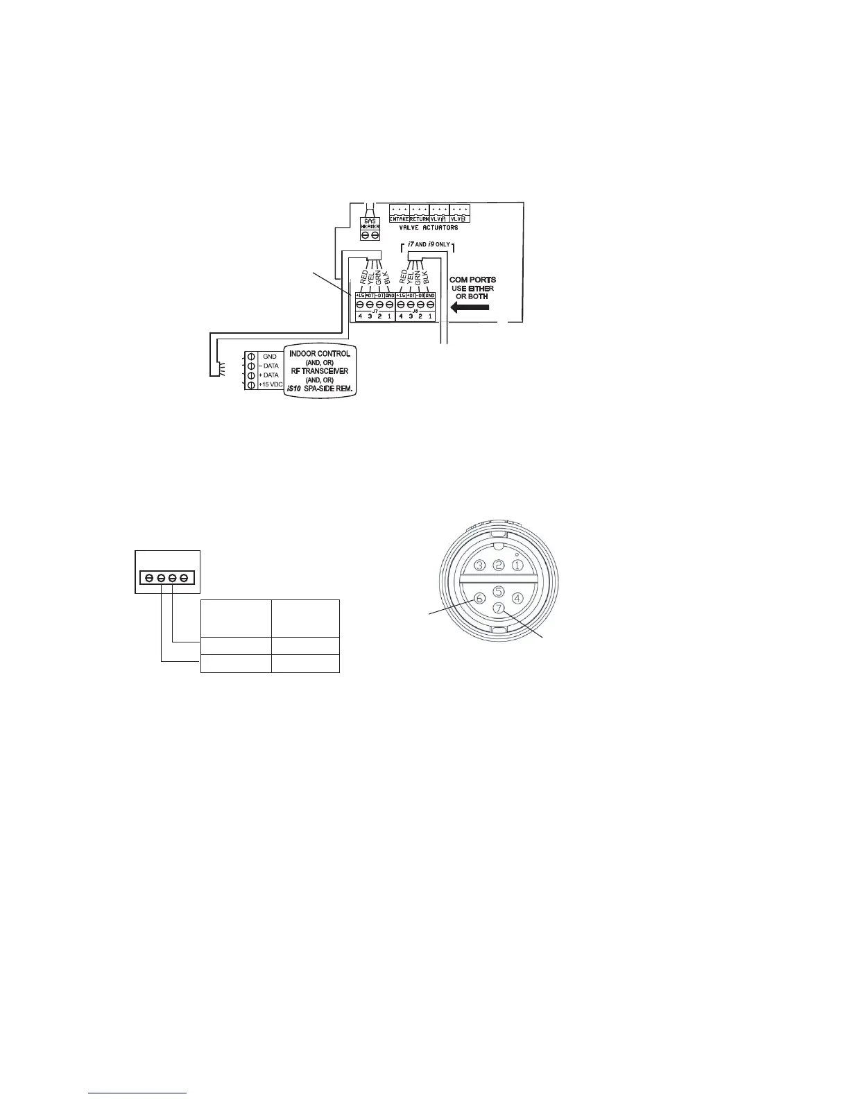
6. Strip back the cable conductors ¼”. Insert the wires into the either of the COM PORTS
(J7 and J8) screw terminals located on the left side of the Personality board. Secure the
wires with the screws. For wiring details, refer to ”Pin Conguration” shown below.
Note: Multiple wires may be inserted into a single screw terminal. Strip back the cable
conductors ¼ inch. Insert the two wires into the screw terminals on the board. Secure the wires
with the screws.
Pin Conguration Pump to IntelliTouch control system pin conguration:
• Pump: Connect pin 6 (green) to IntelliTouch screw terminal pin 2 (green)
• Pump: Connect pin 7 (yellow) to IntelliTouch screw terminal pin 3 (yellow)
7. Close the control panel into its original position and secure it with the two access screws.
8. Install the high voltage cover panel and secure it with the two retaining screws.
9. Close the load center front door. Fasten the two spring latches.
10. Switch the power on to the load center.
Pin conguration
IntelliTouch COM port (J7/J8)
screw terminal
Pin 6
(Green)
Pin 7 (Yellow)
Pump connector pin conguration
IntelliTouch Personality
board COM PORT
(J7/J8)
IntelliTouch
screw terminal
connector
IntelliFlo
(2-wire cable)
2 (GRN) GREEN (Pin 6)
3 (YEL) YELLOW (Pin 7)
 Loading...