MASTERTEMP 125 Pool and Spa Heater Installation and User’s Guide P/N 475114 Rev. F 8/2020
16 |
Lead
Anchor
For Heater mounting
bolts and clamps,
purchase separately
Bolt Down Bracket Kit,
Part No.
460738.
Figure 22.
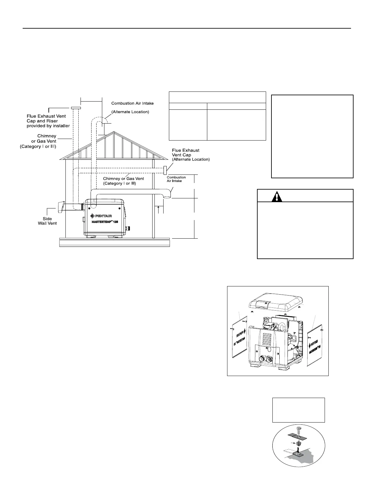
Door Acess Panel
Top Panel
Door Acess Panel
CONTROL PANEL POSITIONING
On an outdoor shelter installation, the exhaust discharges into a vent
pipe. Orient the heater so that the vent pipe does not interfere with
adjustment of the operating controls. The control panel located on
the top panel can be rotated to any of the three sides of the heater for
easy access, see Figure 21.
1. Remove the bolts from the door panels. Remove both door access
panels.
2. Remove the four corner nuts that secure the top panel. Lift the
top panel upward to remove the top panel.
3. Rotate the top panel to the desired position located at 90° angles.
Note that the control panel must NOT be located on the side where
the vent is located.
4. Replace the top panel down onto the side panels. Be sure that
there are no wires caught under the panel.
5. Secure the top panel using the four corner nuts.
6. Reattach the door access panels.
FINAL INSTALLATION CHECK
After installation, the installer MUST test and check that the heater is operating and
functioning properly. Some building codes require that the heater be anchored to the
equipment pad or platform to withstand high wind pressures created during hurricanes.
A Bolt Down Bracket Kit, P/N 460738, is available with anchor clamps designed to hold
the unit to the equipment pad in high wind conditions, see Figure 22. Installation of the
anchor clamps are recommended in all installations.
Figure 21.
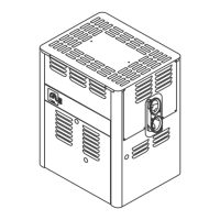
Combustion PVC Air Intake 3 in. Pipe
(Vertical or Horizontal)
No. of 90° Elbows Maximum Length in M (ft)
0 (21.3 M) 70 ft.
1 (17.7 M) 58 ft.
2 (14.0 M) 46 ft.
3 (10.4 M) 34 ft.
4 (6.7 M) 22 ft.
15.24 cm (6 in) min.
30.4 cm (12 in) min.
91.44 cm (36 in) min.
30.4 cm (12 in) min.
7.62 cm (3 in)
PVC Pipe
7.62 cm (3 in) PVC Pipe
91.44 cm
(36 in) min.
NOTE:
Each 90-degree elbow reduces
the maximum horizontal PVC
air intake duct run by 3.6 m
(12 ft.) and each 45-degree
elbow in the PVC air intake
duct run reduces the maxi-
mum run by 1.8 m (6 ft). See
the Table above for the maxi-
mum lengths using 90-degree
WARNING!
DO NOT USE PVC PIPE FOR FLUE
EXHAUST VENT. FLUE EXHAUST
VENT TEMPERATURES CAN BE IN
EXCESS OF 204° C. FLUE EXHAUST
VENT MUST BE CATEGORY I or
CATEGORY III METAL VENT.
Direct Air Intake Duct with 76 mm (3 in - UK) PVC Pipe (Indoor Installation)
For indoor heater installations where combustion air supply might be insufcient, the MasterTemp
125 Heater is
certied for a direct air intake duct using 76 mm (3 in - UK) PVC pipe (Pentair P/N 461031). If outside air is drawn
through PVC duct directly into the heater, PVC pipe can be installed in accordance with the following requirements:
The air intake opening MUST be installed at least 30.5 cm (12 in) above the roof line or normal snow levels for free
air ow. The Category I or III exhaust vent termination cap must have at least 1.8 m (6 ft.) minimum vertical clearance
from air intake duct (see Figure 20 below).
Figure 20.
Section 1. Installation