20
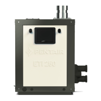
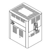
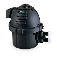
MAX-E-THERM
®
Pool and Spa Heater Installation and User’s Guide P/N S794 Rev. H 8-11-14
VENT INSTALLATION – INDOOR INSTALLATION (U.S.) OR OUTDOOR SHELTER (CANADA)
(Category I)
Always vent the heater to the outdoors, see Note*.
• Vent it vertically using Type “B” double wall vent connector pipe.
Locate the heater so as to minimize the length of horizontal venting and the number of vent elbows required. Horizontal
vent runs must slope up 1/4" per foot (2cm/M) from the heater to allow exhaust condensate to drain and it is recommended
to have a condensate drain as described in the venting installation instructions.
VERTICAL VENTING
- NEGATIVE PRESSURE
(See Figures 13, 14 and 15)
Vent the heater vertically in a negative pressure (positive draft) system in
accordance with the National Fuel Gas Code, ANSI Z223.1/NFPA 54 and/or
CSA B149.1, Natural Gas and Propane Installation Codes, and local codes. Type
“B” Double-wall vent connector is recommended; however single-wall pipe is
allowed by the National Fuel Gas Code in some circumstances. Consult your
local code official for detailed information. Do not use a draft hood with this heater.
To connect a negative pressure metal gas vent to the heater, order the appropriate
Metal Flue Collar from the chart below:
Section 2. Installation
Co
b
stio
Chambe
Flue Collar
4" x 8" Metal
Flue Collar
Clean the Interior Surface
Vent Pipe
Clean and RTV
This Su
face
Figure 13.
1. See Table 10, to determine allowable vent sizes for your heater.
NOTICE: Table 10 is for installations in which the total lateral vent length (that is, the horizontal distance from the flue
collar to the main vertical portion of the vent) is less than 1/2 the total vent height (the vertical distance from the flue collar
to the vent termination) and which have three or less elbows in the system. For venting systems
which do not meet these
conditions, consult the National Fuel Gas Code, ANSI Z223.1 (U.S.), or the standards CSA B149.1 and B149.2 (Canada).
Read “VERTICAL VENTING – NEGATIVE PRESSURE” before using this table.
Table 10.
– Permitted Minimum and Maximum Vent Heights By Size and Heater Model
NOTE *: Vent must be at least eight (8) feet away from
nearest vertical surface. Vents extending five (5) feet or
more above the roof must be braced or guyed.
Consult your local code officials for detailed information.
ralloCeulFlateM.oNtraP
"6x46700-70777
"8x47700-70777
)sreteM(teeFnirotcennoCllaW-elbuoD"B"epyThtiwtneVllaW-elbuoD"B"epyT
eziStneV
002ledoM
.xam/.nimthgieH
333
ledoM
.xam/.nimthgieH
004ledoM
.xam/.nimthgieH
.ni6)5.03(.tf001/)8.1(.tf6)5.03(.tf001/)9(.tf03.ceRtoN
.ni7)5.0
3(.tf001/)8.1(.tf6)5.03(.tf001/)3(.tf01)5.03(.tf001/)6.4(.tf51
.ni8)5.03(.tf001/)8.1(.tf6)5.03(.tf001/)8.1
(.tf6)5.03(.tf001/)4.2(.tf8
.ni01dna9)3.51(.tf05/)8.1(.tf6)5.03(.tf001/)8.1(.tf6)5.03(.tf001/)8.1(.tf6
)sre
teM(teeFnirotcennoCllaW-elgniShtiwtneVllaW-elbuoD"B"epyT
eziStneV
002ledoM
.xam/.nimthgieH
333ledoM
.xam/.
nimthgieH
004ledoM
.xam/.nimthgieH
.ni6)6.4(.tf51/)8.1(.tf6.ceRtoN.ceRtoN
.ni7)4.2(.tf8/)8.1(.tf6)6(.tf02/)3(.
tf01)3.51(.tf05/)6.4(.tf51
.ni8.ceRtoN)6(.tf02/)8.1(.tf6)6(.tf02/)4.2(.tf8
.ni9.ceRtoN.ceRtoN)8.1(.tf6/)8.1(.t
f6
.ni01.ceRtoN.ceRtoN.ceRtoN
 Loading...