K-System – Isolated Barriers
Technical Specifications
DOCT-0187Y 2023-12
45
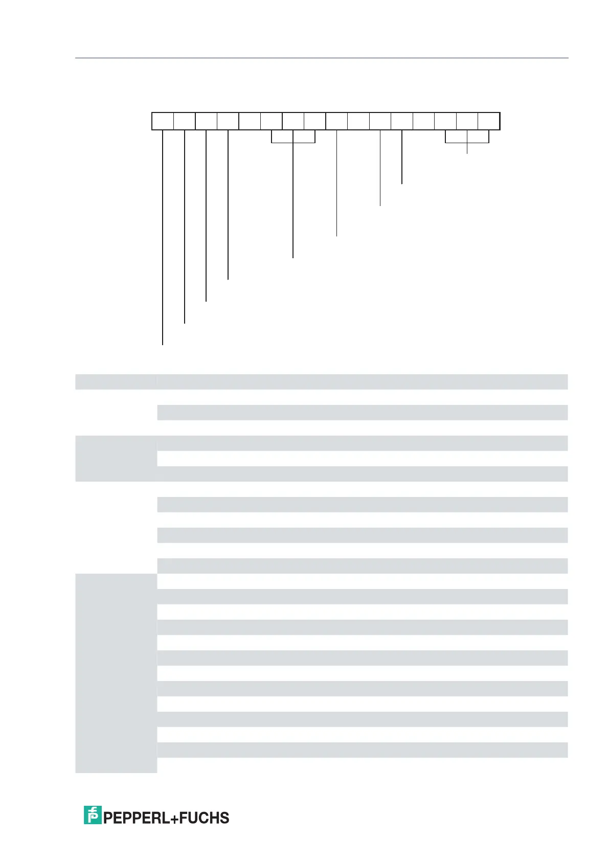
7.2 Model Number Description
K - -Ex .
1 System
2 Construction type
3 Type of power supply
4 Level of power supply
9 Special function,
if available
8 Number of channels
7 Isolated Barriers,
not applicable to Signal Conditioners
6 Device generation (2 to X)
5 Device function
Position 1 K K-System
Position 2 C Version with removable terminal blocks, 12.5 mm width
F Version with removable terminal blocks, 20 mm or 40 mm width
H Version without removable terminal blocks, 20 mm or 40 mm width
Position 3 D DC power supply
A AC power supply
U AC/DC power supply
Position 4 0 without power supply
2 24 V
4 100 V
5 115 V
6 230 V
8 24 V DC or 115/230 V AC
Position 5 CC Converter for current/voltage
CD Active current driver
CR Transmitter power supply, current output
CRG Transmitter power supply with trip value
CS Passive current driver
DU Switch amplifier, time relay
DWB Overspeed/underspeed monitor, logic control unit
EB Power feed module
ELD Ground fault detection
ER Conductivity switch amplifier
FF RS 232 repeater
GS Trip amplifier for current/voltage
GU Universal trip amplifier
 Loading...