1/01 E Service Instructions 6
Knife Drive
The timing of the S52, S53, S54
control switches on the crank-
shaft is explained by a chart in
the "Knife Control" section (con-
trol switches).
The proper functioning of the con-
trol switches can be checked from
the service menu (I/O Test).
S53
- Knife-down travel.
- Clamp locking while the knife is
coming down.
S54
- Checking the UDC.
- Emergency shut-off in case of
S52 failure.
The gap shown in the timing
chart (switching distance) be-
tween S54 and S53 should be
1/3 to 1/2 of a flywheel turn. For
this purpose, energize the clutch
(refer to "Manual Cranking" in the
Operating Instructions manual)
and check the switching distance.
When the knife drive is automati-
cally stopped, the knife edge must
protrude at least 6 mm over the
right-hand clamp bottom edge.
Setting the
Automatic Stopping
Device
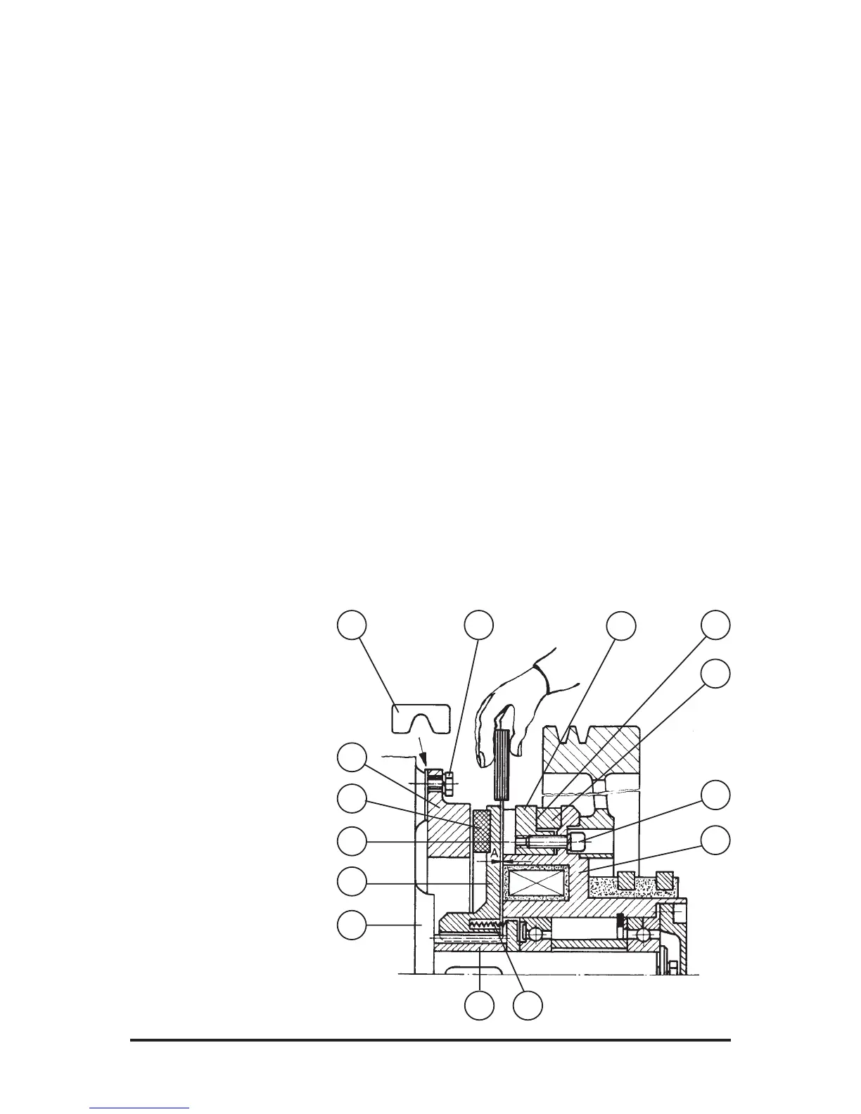
Fig. 3
8
9
7
54
6
1
2
3
14
11
12 13 10
The cam of S52 should be set
so that the machine would stop
at the upper dead centre and
the cam follower of S54 comes
to stop within the first third of
its cam length.
When the knife beam runs over
the UDC (S54 no longer oper-
ated at stop position), any subse-
quent cut triggering is disabled.
The display reads Error 28:
Safety Module Detecting Error.
By pressing the "C" key, concrete
Error 7 appears: Knife Overrun.
After turning off and on the ma-
chine, the subsequent cut can be
restarted by the knife pushbut-
tons.
If there is another overrun at the
UDC, slight pre-stopping correc-
tion can be performed by turning
forward the entire cam package
within the permissible range.
If such correction by the above-
mentioned cam shifting is not
successful, i. e. if there is still
overrun, checking the clutch/
brake assembly of the knife drive
should, under any circumstances,
be checked.
The control switches have the
following function:
S52
- Taking over knife up-movement
from the lower dead centre (LDC).
- Deactivating the light guard ef-
fect.
- Stopping the knive travel to-
wards the upper dead centre
(UDC).
Knife Drive Clutch
and Brake Assembly
System Design (Fig. 3)
Armature disk 3 provided with
brake lining 1 or clutch lining 2,
respectively, is axially movable
on a spline bushing. It is forced
against brake ring 6 by springs 5.
This reliably brakes the machine.
When the clutch is energized,
armature disk 3 is attracted by
the magnetic field of coil body 7
and pressed against friction ring
8. The machine is engaged.