10
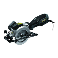
OVERVIEW COMPONENTS
A - Saw blade K - Lower guard
B - Switch L - Base plate
C - Lock button M - Storage for hexagon key
D - Upper guard N - Spindle lock
E - Angle locking lever O - Depth locking lever
F - Parallel guide lock screw P - Depth scale
G - Parallel guide Q - Dust outlet
H - Clamping flange R - Dust pipe
I - Clamping screw S - Machine housing
J - Lower guard guide lever
ASSEMBLY
Check for damage to the tool, parts and accessories which may have occurred during transportation.
Take some time to read this manual carefully and understand all the content prior to assembly and
operation.
CAUTION
Always ensure that the tool is switched off and unplugged from the main supply
before assembly.
Changing the Blade
- Place the saw on the side of a flat surface.
- Rotate the saw blade (A) by hand while depressing the Spindle Lock Button (N) until the blade is
locked, Turn the blade clamp screw (I) by using the provided hex key in a clockwise direction
.
- Remove the blade clamp screw (I) and the outer flange (H).
- Open the lower guard (K) by moving the lower guard lever (J), remove the blade.
- Clean the saw blade flanges, mount the new saw blade onto the spindle.
Fig. 1
A
B
C
D
E
F
G
H
I
J
K
L
M
N
O
P
Q
E
RS
 Loading...