Assembly and adjustments (continued)
WARNING: Do not plug the router table power cord into an outlet until the table is fully
assembled and the router is installed.
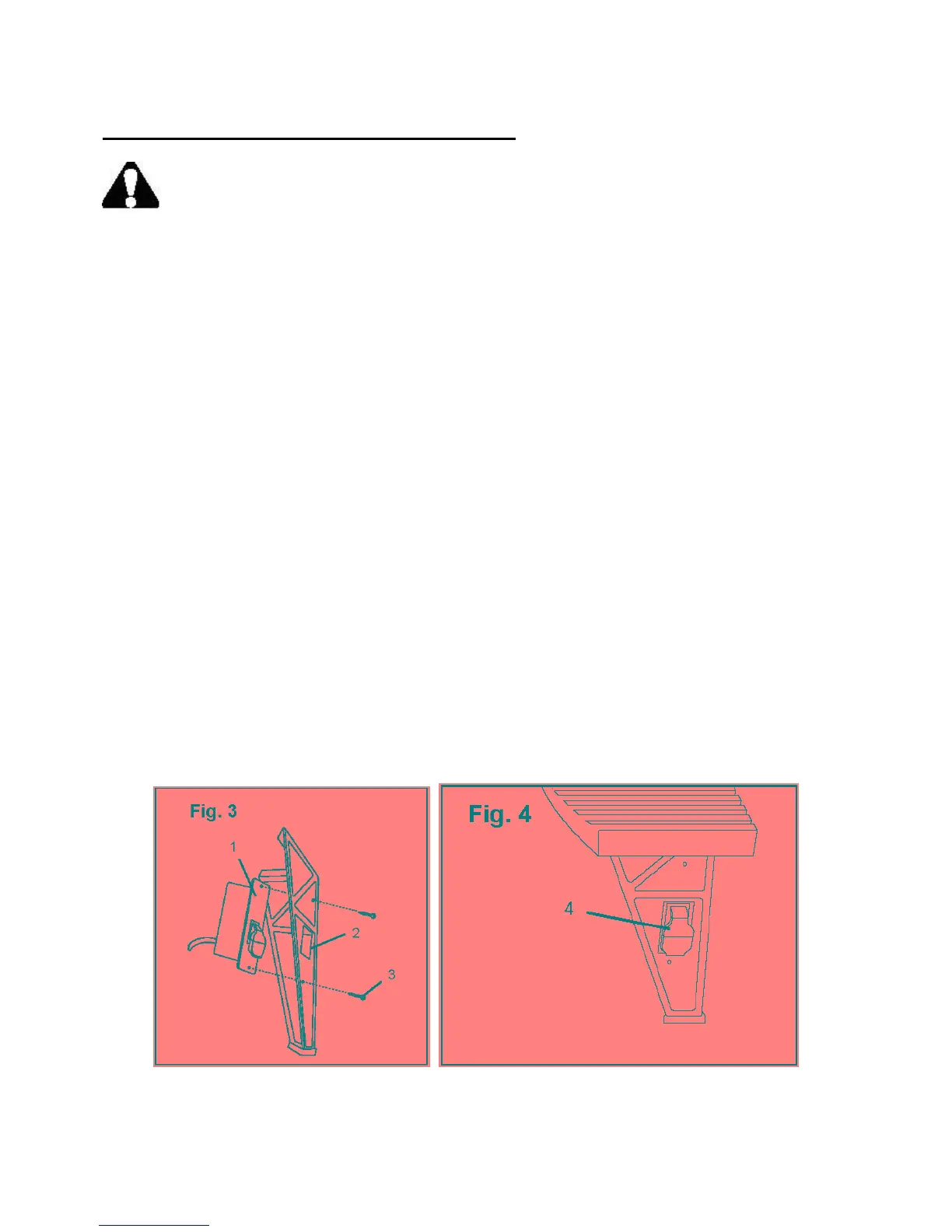
Attach the switch box to the front leg (Fig. 3 and 4)
The switch box fits into the rectangular cutout on the right front leg so that the switch is easily
accessible. The switch on the front of the switch box fits through the cutout in the leg. An electric
cord and a double-insulated electric outlet for the router are located on the rear of the switch box.
Note: If the cutout is not on the right front leg when the table is upright, reinstall the legs.
1. Place the switch box (1) through the cutout (2) on the front right leg.
2. Align the screw holes at the top and the bottom of the switch box with the 2 small openings
above and below the cutout on the leg.
3. Secure the switch box to the leg with the two small Phillips® head screws (3).
4. Flip the switch (4) up and down to make sure it moves freely.
Note: The switch has a safety lock that must be in place before you will be able to flip the switch
up or down.
Secure the table to a work base (optional)
Each table leg has an opening at the bottom for securing the assembled table to a suitable base. The
work base should be level and strong enough to support the weight of the table and the router. In
addition, the work base should be very stable to eliminate vibration and wobble when the router is
operating.
Select a suitable work base and use an appropriate fastener to secure each table leg to the work base.
12