ENG
Operating Manual | Attachment and Installation Cooling Units | Standard Controller (SC) – 400 / 460 V, 3~ | 086100125 37/66
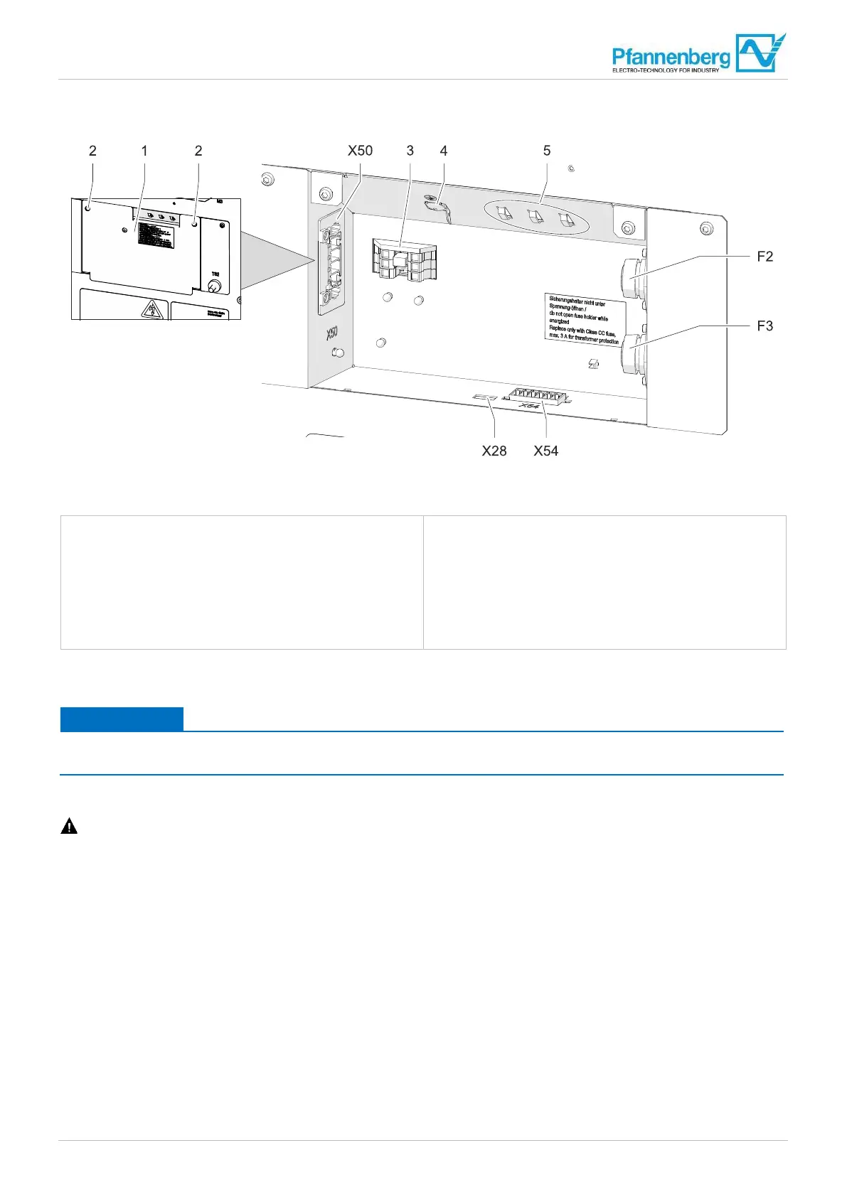
4.6.3 Connection compartment
Fig. 1
5: Connection compartment
1 C
over plate
2 Screws (2×) for cover plate
3 Plug-in bridges for mains voltage adaptation
4 Grounding connection for cover plate
5 Cable tie eyes for strain relief
X50 Terminal strip mains connection
X51 Terminal strip multimaster control
(only for MC-Controller)
X54 Terminal strip fault indication/door contact
X28 Service interface
F2 Control voltage fuse
F3 Control voltage fuse
The units are connected electrically in the connection compartment. The connection compartment is on the back of the unit
behind the cover plate.
The UL approval is voided if the cover plate is not mounted.
• Only operate the unit with the cover plate mounted.
Prerequisite
DANGER – Danger to life due to electric shock. Make sure that the unit is voltage-free.
• All general requirements for safe and reliable operation are fulfilled.
Procedure
1. Loosen the screws (2) on the cover plate (1) and remove the cover plate. Pull off the grounding connection (4) for the
cover plate.
2. Strip the connecting cables and fasten to the cable tie eyes (5) with cable ties for strain relief.
3. Make the electrical connections according to the circuit diagram and the following chapters.
4. Plug on the grounding connection (4) for the cover plate and fix the cover plate with the screws (2).
The cooling unit is connected electrically.