ENG
Operating Manual | Attachment and Installation Cooling Units | Standard Controller (SC) – 400 / 460 V, 3~ | 086100125 38/66
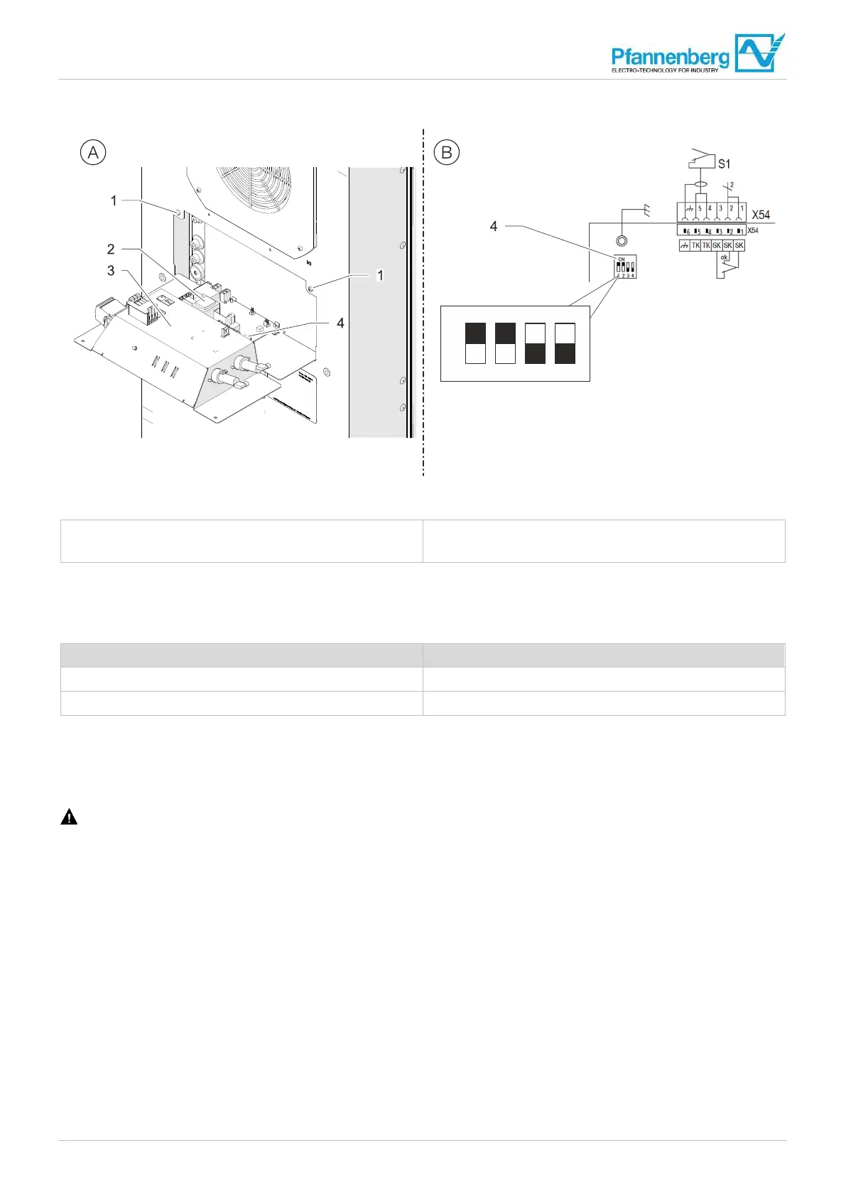
4.6.4 Setting the DIP-switch
Fig. 1
6: Setting the DIP-switch
1 F
astening screws (card cage)
2 Controller
3 Card cage
4 DIP-switch
The DIP-switch on the controller facilitates the setting of the target and limit values for temperatures.
The default factory setting of the values in the delivery condition is as follows:
Parameters Factory setting
Setpoint of the switch cabinet temperature 35°C
Maximum value of the switch cabinet temperature 50°C
Tab. 8: Factory setting of the DIP-switches on the controller
4.6.4.1 Setting the temperature range on the DIP-switch
Prerequisites
DANGER – Danger to life due to electric shock. Make sure that the unit is voltage-free.
• Wait for the end of the 10-minute discharge phase of the electrical components. The unit should only be opened
afterwards.
Procedure
1. Loosen the two fastening screws (1), see Fig. 16 (A).
2. Fold the card cage (3) carefully forward, see Fig. 16 (A).
3. Set the DIP switch (4) on the controller (2) according to "DIP-switch setting possibilities", Page 39, see Fig. 16 (B).
– The settings of the DIP-switch are taken over during commissioning.
The new temperature range is set on the DIP-switch.