5.4.1 Securing vacuum pump on site
Motor voltage [V] Frequency [Hz] Rated (nominal) cur-
rent [A]
Recommended fuse,
slow-blow [A]
115 ± 10%
115 ± 10%
50
60
2.3
2.9
6
6
230 ± 10%
230 ± 10%
50
60
1.0
1.5
4
4
100 – 115 / 200 – 230 ±5%
100 – 115 / 200 – 230 ±5%
50
60
2.6/1.1
3.1/1.3
6/4
6/4
Tbl. 5: Recommended fuse ratings for on-site fuse protection
On-site fuse protection
►
For the protection of the motor in case of malfunction, always provide fuse protection according to
the regulations applicable for the region.
5.4.2 Setting voltage range of motor
The sticker for the pre-set motor voltage on the cover of the terminal box indicates the set voltage
range.
Prerequisites
●
Mains voltage determined on site
●
Vacuum pump disconnected from mains
Required tools
●
Crosshead screwdriver
40μF 250 V
115 V
6
5
2
3
4
7
1
10μF 450 V
230 V
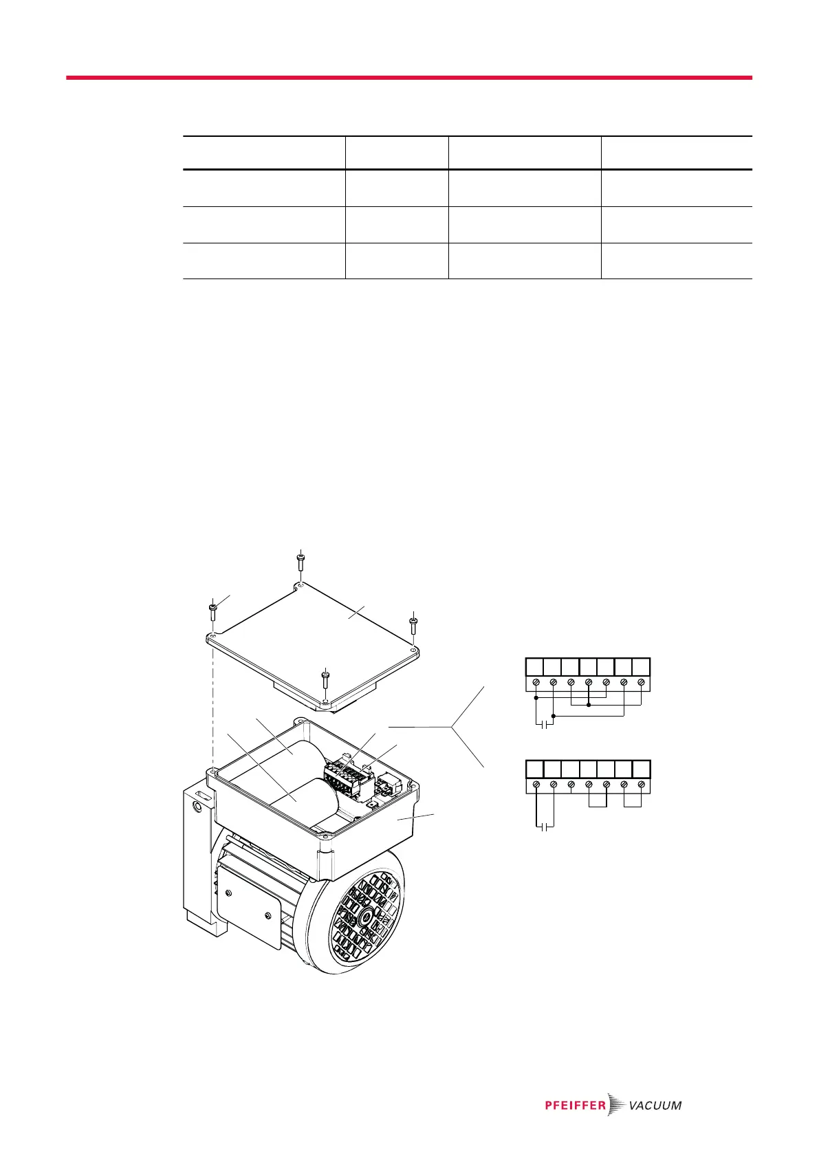
Fig. 9: Opened motor terminal box
1 Cover 5 Capacitor for high voltage (200 – 230 V ±5%)
2 Printed circuit board connector (female) 6 Capacitor for low voltage (100 – 115 V ±5%)
3 Rail connection block (male) 7 Screw, 4×
4 Terminal box
Installation
27/64
 Loading...