7.5 Disassembling and cleaning gas ballast valve
7.5.1 Disassembling and cleaning gas ballast valve (standard version)
The gas ballast valve is soiled if the vacuum pump takes in ambient air containing dust.
Required tools
●
Allen key, WAF 2
●
Snap ring pliers, J0
●
Calibrated torque wrench (tightening factor ≤ 2.5)
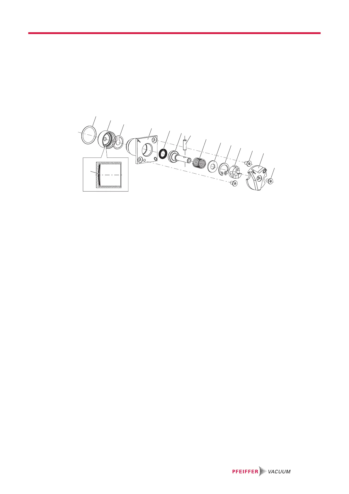
Fig. 16: Gas ballast valve
A Arched side 8 Compression spring
1 O-ring 9 Washer
2 Screw cap 10 Circlip
3 Valve flap 11 Cam plate
4 Valve housing 12 Countersunk screw, 2×
5 O-ring 13 Head
6 Tappet 14 Countersunk screw
7 Cylinder pin
Dismantling gas ballast valve
1. Unscrew and remove the countersunk screws (2×) from the valve housing.
2. Pull the valve housing out of the vacuum pump stand.
–
Be careful with the o-ring.
3. Unscrew the screw cap from the valve housing.
4. Watch out for the valve flap in the valve housing.
5. Rotate knob to “open” position.
6. Unscrew the countersink screw the from the head.
7. Remove the head.
8. Pull tappet far enough out of valve housing so that you can pull out cylinder bolt.
9. Remove the cam plate and the circlip using snap ring pliers.
10. Be careful with washer and compression spring.
11. Remove tappet from valve housing.
–
Be careful with the o-ring.
12. Clean all parts and check parts for wear.
13. Replace wear parts according to maintenance kit.
Assembling gas ballast valve
1. Insert o-ring into groove in tappet.
2. Insert the tappet in the valve housing.
3. Install compression spring and washer.
4. Install the circlip in the recess in the valve housing.
5. Slide the cam plate onto the tappet.
–
Take care with longitudinal groove in flange housing.
6. Pull out the tappet against the force of the spring and place the cylinder bolt in the bore.
7. Rotate cam plate to move tappet to "1" position (open).
8. Install knob to tappet.
9. Tighten the countersunk head screw.
–
Tightening torque: 1.0 Nm.
Maintenance
43/64
 Loading...