List of figures
Fig. 1: Position of sticker on product, using the M version as an example 9
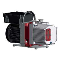
Fig. 2: Structure of the rotary vane pump, using the M version as an example 18
Fig. 3: Rotary vane vacuum pump functional principle 19
Fig. 4: Transporting the vacuum pump manually 21
Fig. 5: Minimum distances and permissible inclination 23
Fig. 6: Vacuum connection with flange connection 24
Fig. 7: Exhaust connection with flange connection 25
Fig. 8: Motor circuit diagram, single-phase motor with switch 26
Fig. 9: Opened motor terminal box 27
Fig. 10: Filling up operating fluid 28
Fig. 11: Gas ballast valve - standard version 32
Fig. 12: Gas ballast valve with inert gas connection 33
Fig. 13: Refilling operating fluid 34
Fig. 14: Draining operating fluid 41
Fig. 15: Remove/fit rotary vane vacuum pump cap 42
Fig. 16: Gas ballast valve 43
Fig. 17: Gas ballast valve with inert gas connection 44
Fig. 18: Dimensions Duo 3 60
Fig. 19: Dimensions Duo 3 M 61
Fig. 20: Dimensions Duo 3 MC 61
List of figures
6/64