Do you have a question about the Phanteks GLACIER Series and is the answer not in the manual?
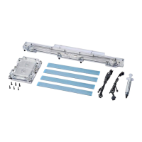
Component included in the package.
Thermal pads included in the package.
Thermal compound included in the package.
Component included in the package.
Screws included in the package.
Screws included in the package.
D-RGB cable for the CPU block.
D-RGB cable for the VRM block.
Unscrew all highlighted screws to remove the stock VRM cooler and backplate.
Unplug the LED and Fan cables when removing the stock cooler.
Use the EVA-Foam from the box as a base for the installation process.
Clean off the original thermal compound, recommending isopropanol alcohol.
Remove protective film and place thermal pads on correct PCB components.
Ensure protective film is removed from both sides of the thermal pads.
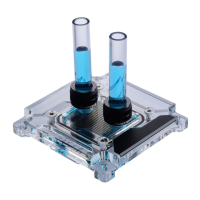
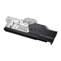
Carefully position the water block onto the motherboard, aligning mounting holes.
Secure the water block with M2.5x10mm and M3x10mm screws to the PCB.
Connect D-RGB cables to the D-RGB strip in both water blocks.
All Phanteks D-RGB products can be daisy-chained together.
Connect the D-RGB cable to the addressable header on the motherboard.
Clean off the original thermal compound, recommending isopropanol alcohol.
Apply a line of thermal paste down the middle of the CPU heatspreader.
Check Intel website for additional installation instructions for LGA 3647 Socket.
Mount the CPU block on the socket and tighten the screws in the instructed order.
Always perform a leak test before providing power to any system components.