11
Scan slice geometry (slice width)
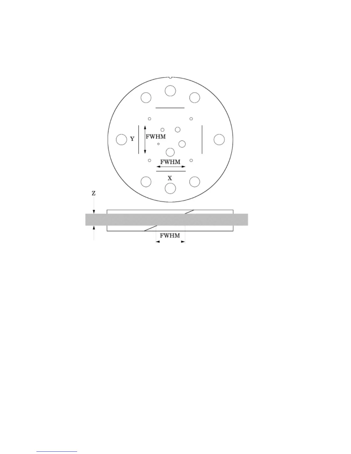
Section 1 has two pair of 23° wire ramps: one pair is oriented parallel to the x axis;
the other pair to the y axis. These wire ramps are used to estimate slice width
measurements and misalignment errors as previously discussed.
The 23° wire ramp angle is chosen to improve measurement precision through the
trigonometric enlargement of 2.38 in the x-y image plane.
To evaluate the slice width (Zmm), measure the Full Width at Half Maximum (FWHM)
length of any of the four wire ramps and multiply the length by 0.42:
(Zmm) = FWHM
*
0.42
To nd the FWHM of the wire from the scan image, you need to determine the CT
number values for the peak of the wire and for the background.
To calculate the CT number value for the maximum of the wire, close down the CT
“window” opening to 1 or the minimum setting. Move the CT scanner “level” to the
point where the ramp image just totally disappears. The CT number of the level at this
position is your peak or maximum value.
To calculate the value for the background, use the region of interest function to identify
the “mean” CT number value of the area adjacent to the ramp.
Using the above CT values, determine the half maximum:
First calculate the net peak... (CT # peak - background = net peak CT #)
Calculate the 50% net peak... (net peak CT # ÷ 2 = 50% net peak CT #)
Calculate the half maximum CT number...
(50% net peak CT # + background CT # = half maximum CT #)