7
Phantom position verication
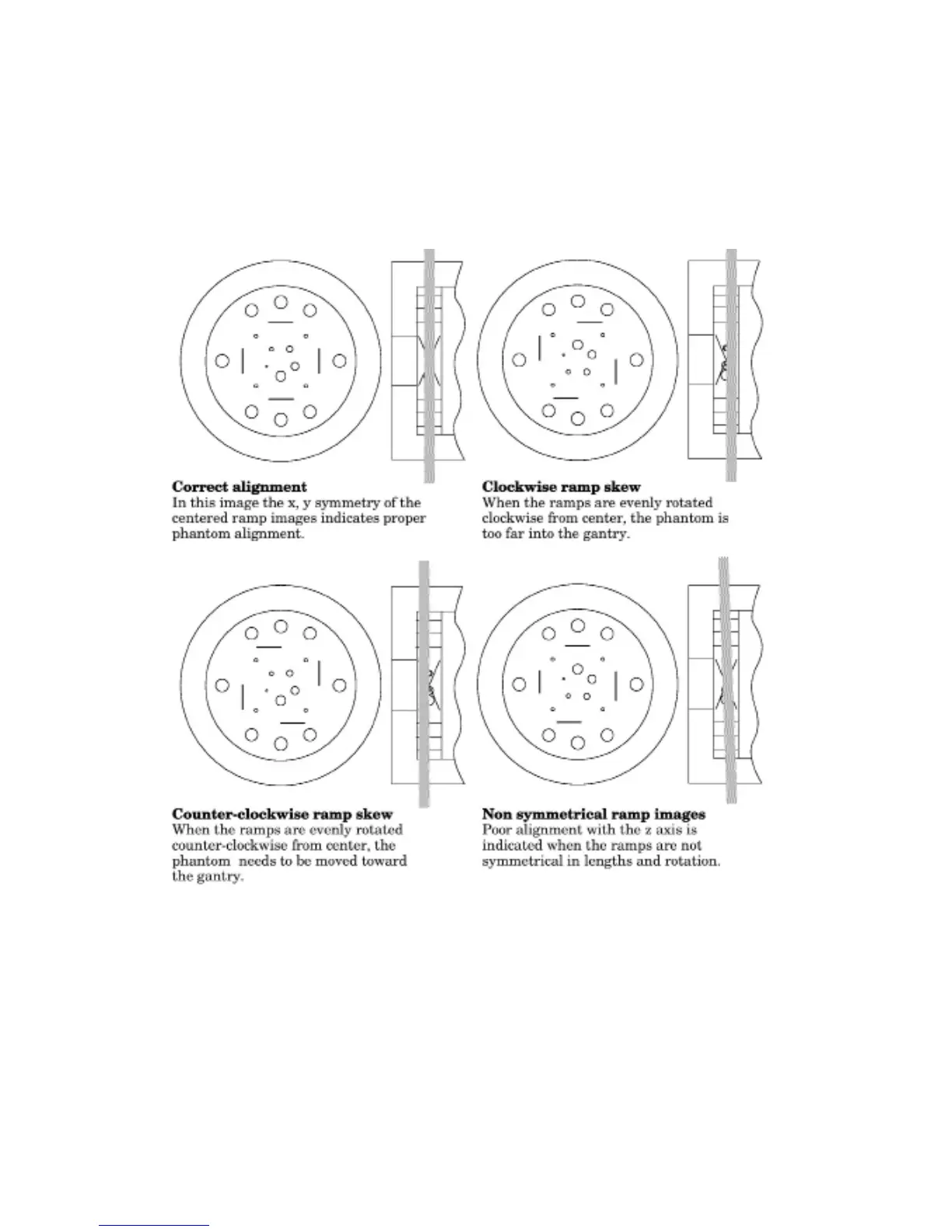
By evaluating a scan image of the CTP404 module the phantom’s position and alignment
can be veried. The section contains 4 wire ramps which rise at 23° angles from the base
to the top of the module. The schematic sketches below indicate how the ramp images
change if the scan center is above or below the z axis center of the test module. The use of
the scanner’s grid image function may assist in evaluation of phantom position.
If misalignment is indicated by the scan image, the phantom should be repositioned to
obtain proper alignment and then rescanned. If the images of the repositioned phantom
duplicate the original misalignment indications, the scanner’s alignment lights may
require adjustment (contact your local service engineer).
Once correct alignment has been established, you can proceed with the tests.