8
Incremental phantom module positioning
The Catphan® 503 phantom is designed so all test sections can be located by precisely
indexing the table from the center of module CTP404 to the center of the other test
modules. The indexing distances from the center of the CTP404 module are listed below.
Catphan® 503 test module locations:
Module Distance from the center of CTP404
CTP528, 21 line pair high resolution 30mm
CTP486, Solid image uniformity module 110mm
Drawings in the manual
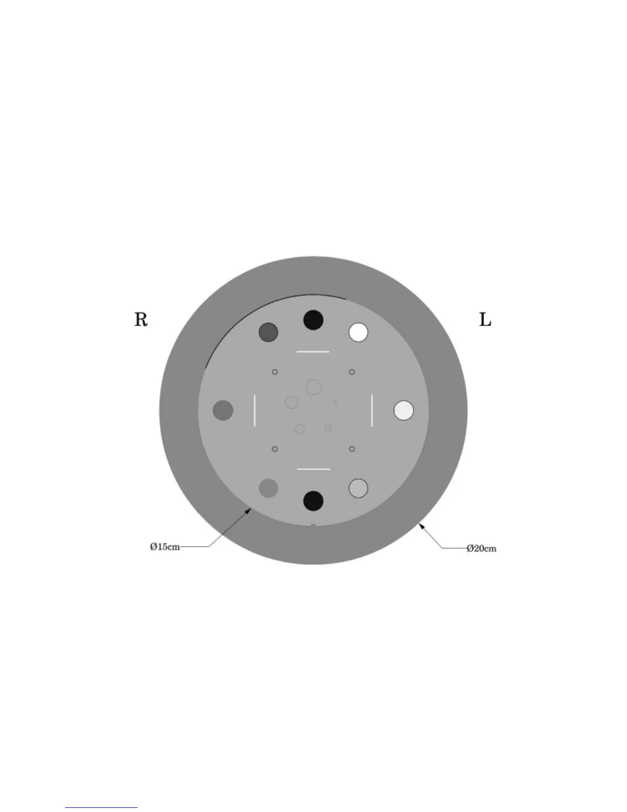
The drawings in this manual show a schematic view of the modules as they would be
seen in a typical head rst CT scan where the right side of the phantom is shown on the
left side of the image.
Most of the schematic drawings show the 15cm diameter module without the 20cm
diameter housing. Please note that the modules are pressed into the housing and
sometimes there is a small air gap that creates a black crescent line between the test
module and the housing. This is shown on the above illustration running from the 10:00
to 12:30 positions. Since this is a radial air gap it will not affect the internal image
measurements if the phantom is centered in the scan eld.