DDC Instructions
24
Lenovo CK5S5
Go to cover page
General
DDC Data Re-programming
Analog DDC IC, & EEPROM
Additional information
In case the DDC data memory IC or main EEPROM which storage all
factory settings were replaced due to a defect, the serial numbers have
to be re-programmed" ".
It is advised to re-soldered DDC IC and main EEPROM from the old
board onto the new board if circuit board have been replaced, in this
case the DDC data does not need to be re-programmed.
Additional information about DDC (Display Data Channel) may be
obtained from Video Electronics Standards Association (VESA). Extended
Display Identification Data(EDID) information may be also obtained from
VESA.
1. An i486 (or above) personal computer or compatible.
2. Microsoft operation system Windows 95/98 .
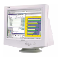
Y o Install the EDID_PORT_Tool under Win2000/XP . As
Fig. 1 .
A. Cody the "UserPort.sys" to C:\WINNT\system32\drivers(win2000)
C:\WINDOWS\system32\drivers(winXP)
B. Running " io.exe" everytime, Before you start to programming
edid data .
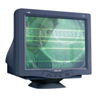
4. A/D Alignment kits (12NC: 3138 106 10079) shown as Fig. 2:
inclusion : a. Alignment box x1
b. Printer cable x1
c. (D-Sub) to (D-Sub) cable x1
D. (DVI-D) to (D-Sub) cable x1
Note: The EDID46.EXE is a windows-based program, which cannot
be run in MS-DOS.
System and equipment requirements
ou have t
3. EDID46.EXE program (12NC: 3138 106 10103) .
Fig. 1Fig. 1
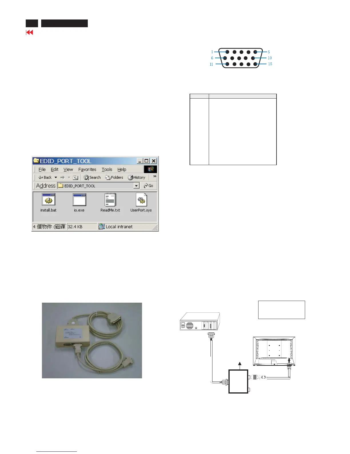
PIN No. SIGNAL
1 Red video input
2 Green video input / sync on green
3 Blue video input
4 GND
5 GND -Cable detect
6 Red video GND
7 Green video GND
8 Blue video GND
9 DDC +3.3V or +5V
10 Logic GND
11 GND
12 Serial data line (SDA)
13 H-sync / H+V
14 V-sync
15 Data clock line (SCL)
Pin assignment
15-pin D-Sub Connector
Configuration and procedure
There is no Hardware DDC (DDC IC) anymore. Main EEPROM stores
all factory settings and DDC data (EDID code) which is also called
Software DDC. The following section describes the connection and
procedure for Software DDC application. The main EEPROM can be re-
programmed by enabling '' factory memory data write'' function on the
DDC program (EDID46.EXE).
Initialize alignment box
In order to avoid that monitor entering power saving mode due
to sync will cut off by alignment box, it is necessary to initialize
alignment box before running programming software
(EDID46.EXE). Following steps show you the procedures and
connection.
Step 1: Supply 8-12V DC power source to the Alignment box by
plugging a DC power cord .
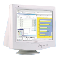
Step 2: Connecting printer cable and D-Sub cable of monitor as Fig. 3
Fig. 3
PC
1=Power connector
2=D-SUB connector
~
~
To printer port (
L
TP1)
DC Power
8-12 V
Printer
Port
To
Monitor
To PC
1
2
----->
----->
Fig. 2