EasyManua.ls Logo

Philips 14PV110/01 - 8. Electrical setting; 8.1 Measuring instruments; 8.2 Setting instructions; 8.3 Settings

Philips 14PV110/01
114 pages
Print Icon
To Next Page IconTo Next Page
To Previous Page IconTo Previous Page
Loading...

 
 




 
 !
" #$%&
'( )
 $
* "
+ ,-!$%&
. 
 '/
0 123
4 %,.5**+64++
5 ,'#.5**+64+*05
 
 
((
'
*#
+
.*
,!-
07
48
5(



9

#:

#*++:++.5;-(2',3
Counter Reading Start
0 0040 ±8 0310 ±12
Video
Blank B&W Pattern Color Bars
Audio
Blank 6kHz (mono) 40Hz, 3kHz, 15kHz (Mono & Stereo)
The element
to be set
Test point: Connection
point for the measuring
instrument (signal)
Operating mode:
Example: SP, Record & Play
Record video signal and play
back section just recorded
TP ADJ. MODE INPUT
Emitter
7513
R3045
SP.Record &
Playback
SCART-Input
White picture
TAPE MEAS. EQ SPEC.
Blank tape
Oscilloscope,
Video Pattern
Generator
1V
pp
±40mV
Required test signal and
signal input:
Example: White picture
video signal to SCART
input
Measuring
instrument
Required value
Tape required for the
setting work
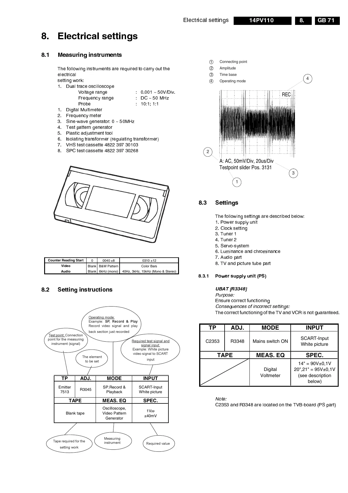
A: AC, 50mV/Div, 20us/Div
Testpoint slider Pos. 3131
REC
4
3
1
2
Connecting point
Amplitude
Time base
Operating mode
1
2
3
4
TP ADJ. MODE INPUT
C2353 R3348 Mains switch ON
SCART-Input
White picture
TAPE MEAS. EQ SPEC.
Digital
Voltmeter
14" = 90V±0,1V
20",21" = 95V±0,1V
(see description
below)

Table of Contents

Related product manuals