EasyManua.ls Logo

Philips 248C3LSB/00(AP) User Manual

Philips 248C3LSB/00(AP)
73 pages
To Next Page IconTo Next Page
Page #1 background imageLoading...
Page #1 background image
Description Page
Important Safety Notice--------------------------------------2
Technical Data--------------------------------------------- ----3
Installation-------------------------------------------------------4
On Screen Display------------------------------------------7~8
Lock/unlock, Aging,Factory mode--------------------------9
---------------------------------10
Mechanical Instructions ------------------------------11~13
Color adjustment --------------------------------------------14
Electrical instruction ----------------------------------17~18
DDC Instructions & Serial Number -----------------21~27
DDC DATA -----------------------------------------------28~29
------------------------30~31
Philips Pixel Defect Policy
FAQs (Frequently Asked Questions)---------------15~16
Firmware Upgrade for CPU-
Horizontal frequencies
30-83kHz
TABLE OF CONTENTS
Description Page
-----------------------------------32
Wiring Diagram----------------------------------------------33
Block Diagram------------------------------------------------34
LED Driver
Control Diagram & C.B.A. -----------------------------41~42
Failure Mode Of Panel -
SAFETY NOTICE
Chassis:
24
REFER
T
O BACK COVER FOR
IMPOR
T
ANT SAFETY GUIDELINES
ANY PERSON
ATTEMPTING T
O
SERVICE THIS CHASSIS
MUST FAMILIARIZE
HIMSELF
WITH THE
CHASSIS
AND BE AWARE OF THE NECESSARY SAFETY PRECAUTIONS
TO BE USED WHEN
SERVICING ELECTRONIC
EQUIPMENT CONTAINING
HIGH VOL
T
AGES.
CAUTION:
USE
A SEPARATE
ISOLATION TRANSFORMER FOR THIS UNIT WHEN SERVICING.
Published by Philips Consumer Lifestyle Copyright reserved Subject to modification JMar 06 2012
Scaler Diagram & C.B.A. ------------------------------35~38
GB
MERIDIAN 3
Troubleshooting---------------------------------------------5~6
Service Tool-----------------------------------------------19~20
248C3LSB/00
inch FHD
General product specification------------------------45~62
Exploded View -----------------------------------------------63
Spare/ arts List-------------------------64
Recommended P
PCBA photos---------------------------------------------------65
Repair tips-------------------------------------------------66~67
Repair Flow chart----------------------------------------68~69
Safety Test Requirments------------------------------------70
LCD Colour Monitor
TFT
Diagram & C.B.A.
-------------------------39~40
LED
Diagram & C.B.A.----------------------------------43~44
248C3LSB/00(AP)
248C3LSB/75
248C3LSB/93
248C3LSB/25
BZL&CTRL BD Replace ---------------------------------------71
Auto Color & User reset
--------------------------------72~73
248C3LSB/01

Table of Contents

Question and Answer IconNeed help?

Do you have a question about the Philips 248C3LSB/00(AP) and is the answer not in the manual?

Philips 248C3LSB/00(AP) Specifications

General IconGeneral
Screen Size24 inches
Resolution1920 x 1080
Panel TypeTN
Refresh Rate60 Hz
Brightness250 cd/m²
Contrast Ratio1000:1
Aspect Ratio16:9
Dynamic Contrast Ratio20, 000, 000:1
USB HubNo
Built-in SpeakersNo
Power Consumption (Standby)0.5 W
Tilt-5/20 degree
SwivelNo
Height AdjustmentNo
PivotNo
Response Time2 ms
ConnectivityVGA, DVI
Viewing Angle (H/V)170°/160°
Viewing Angles170° (H) / 160° (V)
VESA Mount Compatibility100 x 100 mm

Summary

Important Safety Notice

LCD Module Handling Precautions

Precautions for handling the LCD module to prevent damage and ensure safety.

Installation Guide

Connecting Monitor to PC

Step-by-step guide for connecting the monitor to a computer.

Troubleshooting Guide

Power and Connectivity Troubleshooting

Addresses power LED status, no picture, and AUTO button issues.

Image Display Troubleshooting

Covers image centering, vibration, and vertical flicker problems.

Screen Appearance Issues

Addresses horizontal flicker, blurriness, distortion, and static image problems.

Audio and Indicator Issues

Solutions for no sound, strong power light, and color dot issues.

Lock, Aging, and Factory Modes

Locking and Unlocking OSD Function

Procedure to lock or unlock the OSD menu controls for user protection.

Accessing Factory Mode

Steps to enter the monitor's factory service mode for advanced settings.

Factory Menu Operations

Details on navigating and using functions within the factory menu.

Accessing Aging Mode

Procedure to activate the aging mode for testing monitor performance.

Philips Pixel Defect Policy

Pixel Defect Policy Overview

Explains Philips' policy regarding acceptable levels of pixel defects.

Color Adjustment Procedures

Monitor Calibration Alignment Procedure

Steps for aligning the monitor using a color analyzer and pattern generator.

Access Factory Mode for Color Adjustment

Steps to enter factory mode to perform color calibration.

White Color Adjustment

White Color Adjustment Procedure

Steps for adjusting white color temperature using CIE coordinates.

Service Tool Hardware

Service Tool Software

FW Writing Tool: Easy Writer

Information on the Easy Writer software used for firmware writing.

DDC Writing Tool: Q-EDID-V30

Details on the Q-EDID software for writing DDC information.

DDC Instructions

DDC Data Re-programming Procedure

Steps for re-programming DDC data memory IC or main EEPROM.

DDC Configuration and Procedure

Steps for setting up and using the PI-EDID software for firmware upgrades.

DDC Connection and Data

DDC Connection and Mains Cord Setup

Instructions for connecting the monitor and mains cord for DDC operations.

EDID Tools Software Operation

Philips EDID Tools Software Setup

Steps to set up the Philips-IMS EDID Tools program for DDC operations.

Launching Q-EDID Software

Instructions for opening the Q-EDID software interface as shown in figures.

DDC File and Serial Number Update

Selecting the 248C3L DDC File

Procedure for opening and selecting the specific DDC file for the monitor model.

DDC Data Loading and Update

Loading DDC File Successfully

Confirmation of successful DDC file loading as illustrated in the figure.

Updating Serial Number (S/N)

Steps to update and correct the serial number within the DDC data.

EDID and Serial Number Writing

Writing EDID and Serial Number

Instructions to execute the "RUN" command to write EDID and serial number.

EDID and Serial Number Update Success

Confirmation of successful EDID and serial number update as shown in the figure.

EDID Reading and Verification

Reading EDID and Verifying Serial Number

Process to read EDID and serial number to confirm successful update.

Firmware Upgrade for CPU

Install Port95nt.exe for Firmware Upgrade

Instructions for installing the Port95nt.exe software and restarting the computer.

Launching NOVATEK Firmware Tool

Steps to open the NOVATEK firmware upgrade tool.

Loading Firmware (.hex) File

Procedure for loading the firmware file into the upgrade tool.

Firmware Upgrade Process

Performing Firmware Upgrade with "Auto"

Steps to initiate the firmware upgrade process by pressing the "Auto" button.

Firmware Upgrade Success Confirmation

Confirmation message indicating a successful firmware upgrade.

LED Driver Diagram & C.B.A

LED Driver IC and Power Supply

Schematic of the LED driver IC, its power supply, and OVP circuit.

Control Diagram & C.B.A

General Product Specification (Revision History)

General Product Specification (Profile)

General Product Specification (Characteristics)

General Product Specification (Panel)

General Product Specification (Frequencies & Electrical)

General Product Specification (Interface Signals)

General Product Specification (DVI Cable)

General Product Specification (HDMI & Timing)

General Product Specification (Modes & OSD)

General Product Specification (Scanning & Power)

General Product Specification (Features)

Perfect Tune II Calibration Procedure

Steps and conditions for performing Perfect Tune II calibration and alignment.

General Product Specification (Visual Tests)

Monitor Color Temperature Adjustment

Details on adjusting color temperature, including preset modes and CIE coordinates.

General Product Specification (Quality Inspection)

General Product Specification (Mechanical)

General Product Specification (Plastics & Base)

General Product Specification (Transportation)

General Product Specification (Stacking & Environment)

General Product Specification (Storage & Disturbances)

Spare and Recommended Parts List

Critical Components List

Identification of critical components and their corresponding part codes and availability.

Repair Tips

General Repair Warnings and ESD Precautions

Important warnings regarding ESD, handling, and tool usage during repair.

Servicing Surface Mounted Devices (SMDs)

Cautions and procedures for handling, storing, and removing SMDs.

SMD Handling and Storage Precautions

Guidelines for preventing oxidation and damage to SMDs during handling.

SMD Removal Techniques

Methods for safely removing small surface-mounted devices using soldering tools.

Cautions During SMD Removal

Precautions to take when using soldering irons and tools for SMD removal.

SMD Attachment and Soldering Procedures

Steps for correctly positioning and soldering SMDs onto the board.

Cautions During SMD Attachment

Precautions for attaching SMDs, including temperature control and solder quantity.

Lead-Free Product Repair Instructions

Lead-Free Product Repair Instructions

Guidelines for using lead-free solder, tools, and techniques for repairs.

Recommended Lead-Free Solder Alloys

Specifies the types of lead-free solder alloys recommended for repairs.

Solder Tools for Lead-Free Repairs

Requirements for solder tools, including temperature capabilities and tip types.

Solder Tool Temperature Adjustment

Recommended temperature settings and precautions for solder tools.

Special Information for Lead-Free BGA-ICs

Precautions for handling and storing lead-free BGA ICs to prevent moisture damage.

Reworking Ball Grid Array (BGA) ICs

Procedures for removing and replacing BGA components, including heating and cleaning.

Repair Flow Charts

Repair Flow Chart: Bad Brightness Issues

Flowchart to diagnose and troubleshoot bad brightness issues in the monitor.

Repair Flow Chart: Bad Image Issues

Flowchart to diagnose and troubleshoot bad image quality problems.

Additional Repair Flow Charts

Repair Flow Chart: No Display Issues

Flowchart to diagnose and troubleshoot when the monitor has no display.

Repair Flow Chart: Control Key Malfunction

Flowchart to diagnose and troubleshoot when front control keys are not working.

Safety Test Requirements

Hi-Pot Test Instructions

Instructions for performing Hi-Pot testing on mains operated products.

Safety Test Application Requirements

Requirements for products undergoing safety tests, including Hi-Pot and Ground Continuity.

Safety Test Methods

Procedures for connecting and performing safety tests like Hi-Pot and continuity.

Safety Test Requirements and Parameters

Specifies test voltages, times, trip currents, and ramp times for safety tests.

Safety Test Equipment and Connection

Details the required equipment and connection setup for safety testing.

Safety Test Data Recording

Requirements for recording and retaining safety test results for a specified period.

Monitor Bezel and CTRL BD Replacement SOP

Bezel and CTRL BD Replacement Suggestion

Suggestion to replace the entire module due to difficulty in separating bezel and CTRL BD.

Module Replacement for Bezel/CTRL BD Failure

Procedure for repairing the entire module when bezel or CTRL BD is non-functional.

M3/M4 Series Auto Color SOP

Auto Color SOP: Step 1 - Factory Mode Entry

Procedure to set input timing and enter factory mode for auto color calibration.

Auto Color SOP: Step 2 - Enable Burn-in Mode

Steps to enable burn-in mode and confirm auto color function.

Auto Color SOP: Step 3 - Disable Burn-in Mode

Final step to disable burn-in mode before exiting factory mode.

M3/M4 Series User Reset SOP

User Reset SOP: Step 1 - Enter User Mode

Instructions to turn on the monitor and enter user mode via the Menu button.

User Reset SOP: Resetting to Factory Defaults

Procedure to select Setup, Reset, and Yes to restore factory settings.

User Reset SOP: Step 2 - Auto Adjustment

Steps to perform auto adjustment after resetting the monitor.
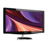
Related product manuals