Circuit Descriptions
EN 27TPS10.1L LA 7.
2013-Apr-26
back to
div. table
7.2 Power Supply
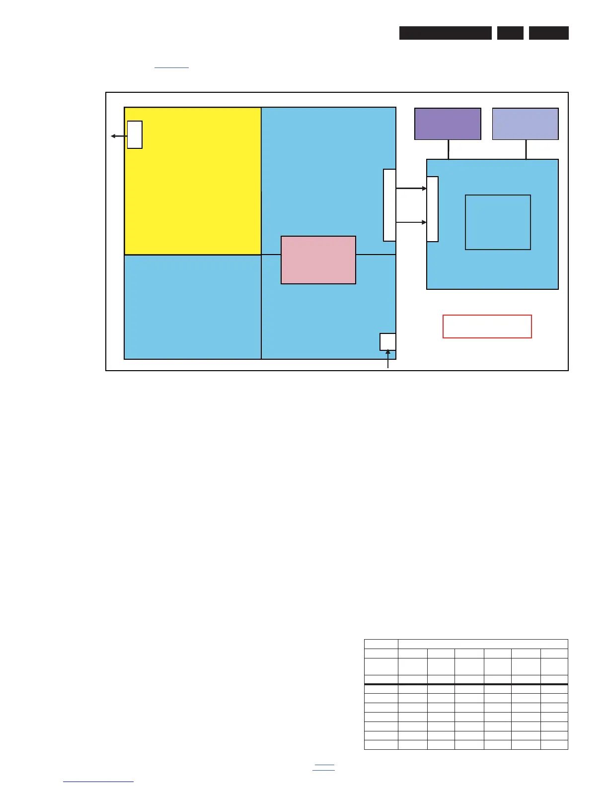
Refer to figure Figure 7-2 for the power architecture of this
platform.
Figure 7-2 Power Architecture
7.2.1 Power Supply Unit
All power supplies are a black box for Service. When defective,
a new panel must be ordered and the defective one must be
returned, unless the main fuse of the panel is broken. Always
replace a defective fuse with one with the correct
specifications! This part is available in the regular market.
Consult the Philips Service web portal for the order codes of the
panels.
Important delta’s with the TPS10.L LA classis platform are:
• New power architecture for LED backlight
• “Boost”-signal is now a PWM-signal + continuous variable.
The control signals are:
• Stand-by
• Inverter “on/off”
• DIM (PWM) (not for PSDL)
In this manual, no detailed information is available because of
design protection issues.
The output voltages to the chassis are:
• +4V7-STANDBY (Stand-by mode only)
• +12V (on-mode)
• +Vsnd (+24V) (audio power) (on-mode)
• +24V (bolt-on power) (on-mode)
• Output to the display; in case of
- IPB: High voltage to the LCD panel
- PSL and PSLS (LED-driver outputs)
- PSDL (high frequent) AC-current.
7.2.2 Diversity
The diversity in power supply units is mainly determined by the
diversity in displays.
The following displays can be distinguished:
• CCFL/EEFL backlight: power panel is conventional IPB
• LED backlight:
- side-view LED without scanning: PSL power panel
- side-view LED with scanning: PSLS power panel
- direct-view LED without 2D-dimming: PSL power panel
- direct-view LED with 2D-dimming: PSDL power panel.
PSL stands for Power Supply with integrated LED-drivers.
PSLS stands for a Power Supply with integrated LED-drivers
with added Scanning functionality (added microcontroller).
PSDL stands for a Power Supply for Direct-view LED backlight
with 2D-dimming.
7.2.3 Connector overview
Table 7-1 Connector overview
Connector
Number CN8101 CN9101 CN8101 CN9101 CN8501 CN9101
Descriptio
n to panel to SSB to panel to SSB to panel to SSB
Pin 121312131213
1 VLED n.c. VLED n.c. VLED n.c.
2 n.c. +5.2V n.c. +5.2V n.c. +5.2V
3 LED1 +5.2V LED1 +5.2V LED6 +5.2V
4 LED1 PS_ON LED1 PS_ON LED5 PS_ON
5 LED1+12VLED1+24VLED4+24V
6 n.c. +12V LED1 +24V n.c. +24V
7 n.c. GND LED1 GND n.c. GND