Circuit Descriptions
EN 28 TPS10.1L LA7.
2013-Apr-26
back to
div. table
7.3 DC/DC Converters
The on-board DC/DC converters deliver the following voltages
(depending on set execution):
• +5V-STANDBY, permanent voltage for the Stand-by
controller
• +3V3-STANDBY, power supply for LED/IR receiver and
controls
• +12V, input from the power supply for the panel
common(active mode)
• +24V, input from the power supply for the AMP
• +1V2, from the power supply for the scaler IC MST6931
• +1V8, supply voltage for MST6931 DDR POWER
• +3V3, genenal supply voltage
• +3V3-TUN, supply voltage for tuner
• +5V nomal supply voltage for headphone AMP
• +5V-USB, input intermediate supply voltage for the USB
Power
• +3V3 from the power supply for the scaler IC MST6931
Figures gives a graphical representation of the DC/DC
converters with its current consumptions:
Figure 7-3 DC/DC converters
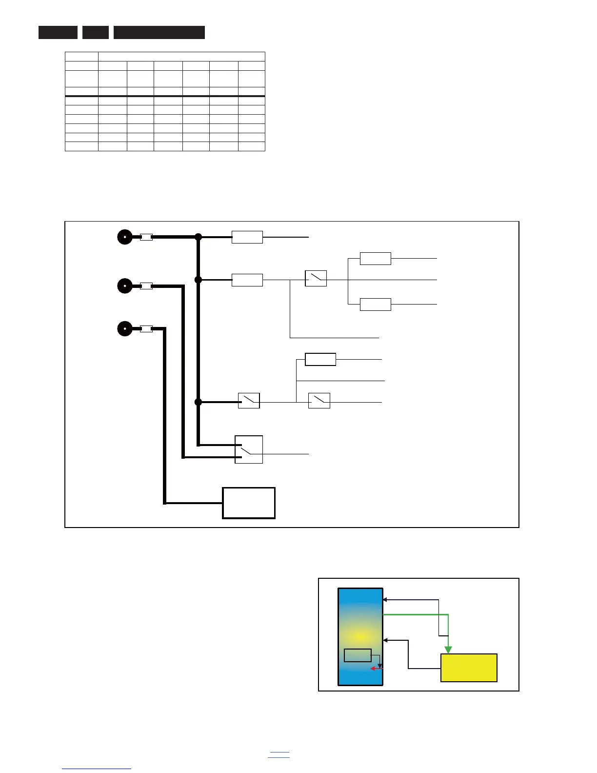
7.4 Front-End Analogue and DVB-T, DVB-C
reception
7.4.1 Front-End Analogue part
The Front-End for analogue tuner consist of the following key
components:
• TUNER LATAM TDST-H030F
• SCALER MST6931XP-SW EPLQFP-128
Below find a block diagram of the front-end application for
analogue part.
Figure 7-4 Front-End DVB-T/C DTV block diagram
8 n.c. GND LED1 GND LED3 GND
9 - GND LED1 GND LED2 GND
10 - +12V LED1 +12V LED1 +12V
11 - +12V n.c. +12V n.c. +12V
12 - DIM VLED DIM VLED DIM
13 - ON/OFF - ON/OFF - ON/OFF
Connector
Number CN8101 CN9101 CN8101 CN9101 CN8501 CN9101
Descriptio
n to panel to SSB to panel to SSB to panel to SSB
Pin 121312131213