Service Modes, Error Codes, and Fault Finding
EN 30 LC8.1U LA5.
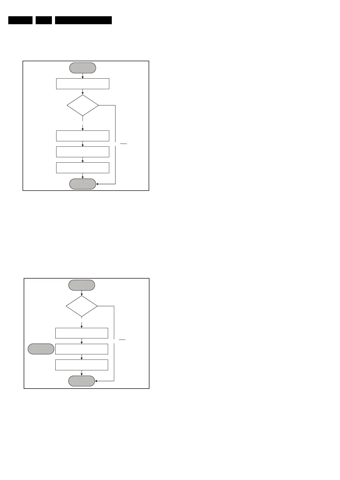
POWERDOWN SEQUENCE
The following figure shows the power-down sequence
flowchart:
Figure 5-11 Power-down flowchart
The power-down condition is detected by the MT5382
POWER_DOWN signal which is an interrupt pin. A “low” level
on this line signifies that power-down is detected. The two
major activities that occur over this operation is the muting of
audio output and write protecting the system flash and
EEPROM.
DC PROTECTION
The following figure shows the DC_PROT interrupt flowchart:
Figure 5-12 DC Protection flowchart
START
MT5382 Detects
POWER_DOWN INT
POWER_DOWN INT
based on falling
edge trigger
Wait for
impending
Power Off
Note: To
Avoid False
Triggering
Write Protect Flash and
System EEPROM
Mute Audio Output
System Idle
Reconfirm
POWER_DOWN
= LOW?
Ye s
No
END
H_17740_036.eps
240108
START
Note: To
Avoid False
Triggering
Log Error Code
Mute Audio Output
Go to STANDBY
Check
DC_PROT = LOW
for 3 sec?
Ye s
No
END
DC Protection
[Protection]
H_17740_037.eps
240108