Circuit Descriptions
EN 23TCM3.2L LA 7.
2009-Jun-19
7.3 Power Supply
All power supplies used in this chassis are a “black box” for
Service. When defective, a new board must be ordered and the
defective one must be returned, unless the main fuse of the
board is broken. Always replace a defective fuse with one with
the correct specifications! This part is available in the regular
market.
Consult the Service Spare Part portal for the order codes of
these boards.
Below some background info on the PSUs is given, to ease the
troubleshooting process in case of power supply problems
7.3.1 Diversity
The only type of power supply used in this platform is the
Integrated Power Board (IPB) - incl. LCD backlight inverters.
Below find an overview of the different PSUs that are used:
Table 7-1 Supply diversity
It should be noted that for different display manufacturers,
different PSUs can be used. When ordering a new PSU,
always check which LCD panel is used in the set, and order the
correct PSU!
7.3.2 IPL32L PSU
Block Diagram
Figure 7-2 Block diagram IPL32L PSU
Key Components
The key component ICs are:
• Stand-by power supply IC: FSQ510 (Fairchild).
• PFC control IC: L6563 (ST).
• 24V PWM control IC: FA5571N (FUJI).
• Inverter high voltage control IC: OZ9976 (O2).
Control Signals
Table 7-2 Control signals
Output Characteristics
Table 7-3 Output characteristics
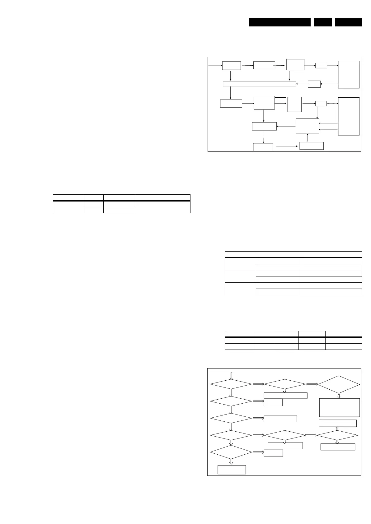
Fault Finding
Figure 7-3 Fault finding diagram IPL32L PSU
Supplier PSU Model Input Voltage Range
TCL
IPL32L 32" LG display
100 - 240 Vac
IPL42L 42" LG display
Control signal Comments Output
PS-ON 3.3V >= ON >= 2.0V AC power output ON
0.7V >= OFF >= 0V AC power output OFF
BL_ON 5.0V >= ON >= 2.0V The inverter is working
1.0V >= OFF >= 0V The inverter is switched OFF
DIMP High level: 2V ~ 5.0V HD: OPC dimming, 140Hz
Low level: 0V ~ 0.7V FHD: PWM, 103.4Hz
Output Voltage Tolerance Min. current Max. current Load regulation
+3V3(STB) +/- 3% 5 mA 200 mA +/- 5%
24V +/- 5% 0.2 A 2.0 A +/- 5%
18520_211_090319.eps
090319
EMC
Filter circu it
Bridge rectifier
Filter circu it
PFC Circu it
IC 1
L1
PWM
Circu it
IC 2
T1
3.3V
Feedback circu it
Protection circu it
S tandby
circu it
IC 3 / T2
T4
HV tra n sformer
INVERTER
Control and
drive circu it
A C IN
BL- ON
High Voltage
AC ou tp u t
Bridge rectifier
Filter circu it
MCU
12V R elay K 1
Opto
cou pler
24V
S ta rtup
S igna l
Circu it
VCC
12V operating voltage
PDIM
PS -ON
395V
18520_212_090319.eps
090319
3.3 V normal?
S witch “on”
P S _ON no rm al?
Relay is clos ed?
PFC voltage
norma l?
Y
Y
Y
Y
N
N
N
N
CB1 voltage
norma l?
PFC_VCC
norma l?
N
24V normal?
Fault
movement
Relay power supply
p art (QB 1) fault
BL_ON and
D IM P normal?
N
Fault
movement
Check S tandb y IC, feed back,
transformer failures , etc.
N
Y
Fuse is open
Whether the
b rid ge rec tif ier
circuit
PFC IC, feedback,
drive f ailure, etc.
Y
PFC power supply
part (Q W 11) fault
Y
PWM IC, feedback,
transformer failures, etc.
N
Y
A ttention : als o check
the PFC andPWM control,
s hort-circuit in order to
rep lace the Fus e and
Bridge.
Y
HV pa rt f ailure
(IC protection
circuit).
such as whether the MOS