Mechanical Instructions
EN 20 Q552.1L LA4.
2010-Dec-29
back to
div. table
2. Lift the rear cover from the TV. Make sure that wires and
flat coils are not damaged while lifting the rear cover from
the set.
4.6.2 Speakers
Each speakerbox unit is mounted with two screws.
When defective, replace the whole unit.
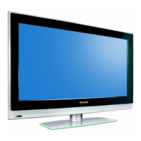
4.6.3 Main Power Supply
Refer to Figure 4-25
for details.
Figure 4-25 Main Power Supply
1. Unplug all connectors [1].
2. Remove the fixation screws [2].
3. Take the board out.
When defective, replace the whole unit.
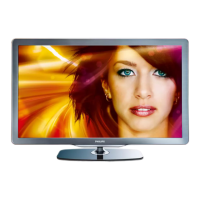
4.6.4 Small Signal Board (SSB)
Refer to Figure 4-26
for details.
Figure 4-26 SSB
1. Unplug all connectors [1].
2. Slide the side cover sidewards [2].
3. Remove the fixation screws [3].
4. Lift the clip [4].
5. Remove the bottom cover downwards [5].
6. Take the board out.
4.6.5 IR & LED Board
Refer to Figure 4-27
for details.
Figure 4-27 IR & LED Board
1. Remove the stand.
2. Remove the IR & LED board cover [1].
Now the IR & LED board can be accessed.
When defective, replace the whole unit.
4.6.6 Keyboard Control Board
The keyboard control panel is mounted on the LCD panel with
two screws.
When defective, replace the whole unit.
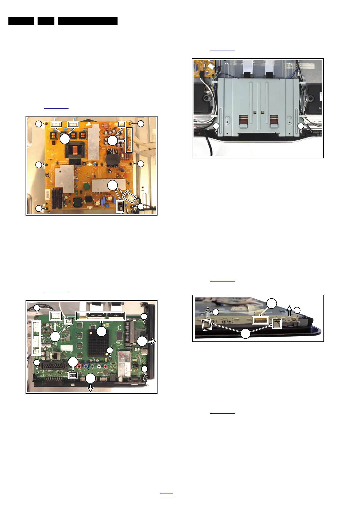
4.6.7 Ambilight Units
Refer to Figure 4-28
for details.
Note: the Ambilight units are to be swapped on PWB level.
Figure 4-28 Ambilight units
1. Unplug the flat foil(s) [1].
2. Release the clips [2] that secure the PWB.
3. Slide the PWB out of the set [3].
4.6.8 LCD Panel
Refer to Figure 4-29
for details.
1. Remove the stand.
2. Remove all boards as described earlier.
3. Remove all cables from the set.
4. Remove the speaker boxes as earlier described.
5. Remove the IR & LED board cover as described earlier.
6. Remove the mains switch [1].
7. Remove the keyboard control panel as described earlier.
8. Remove the clamps [2]. Pay attention to the positioning
of the different screws!
9. Remove the plastic clamps [3].
10. Tilt the clamps [4] after having removed the screw.
18771_108_100504.eps
100504
1
1
1
2
22
22
2
2
2
18771_109_100504.eps
100505
1
4
2
5
1
3
3
3
3
3
18771_110_100504.eps
100504
31 31
18771_111_100504.eps
100504
3
3
2
1