9-5
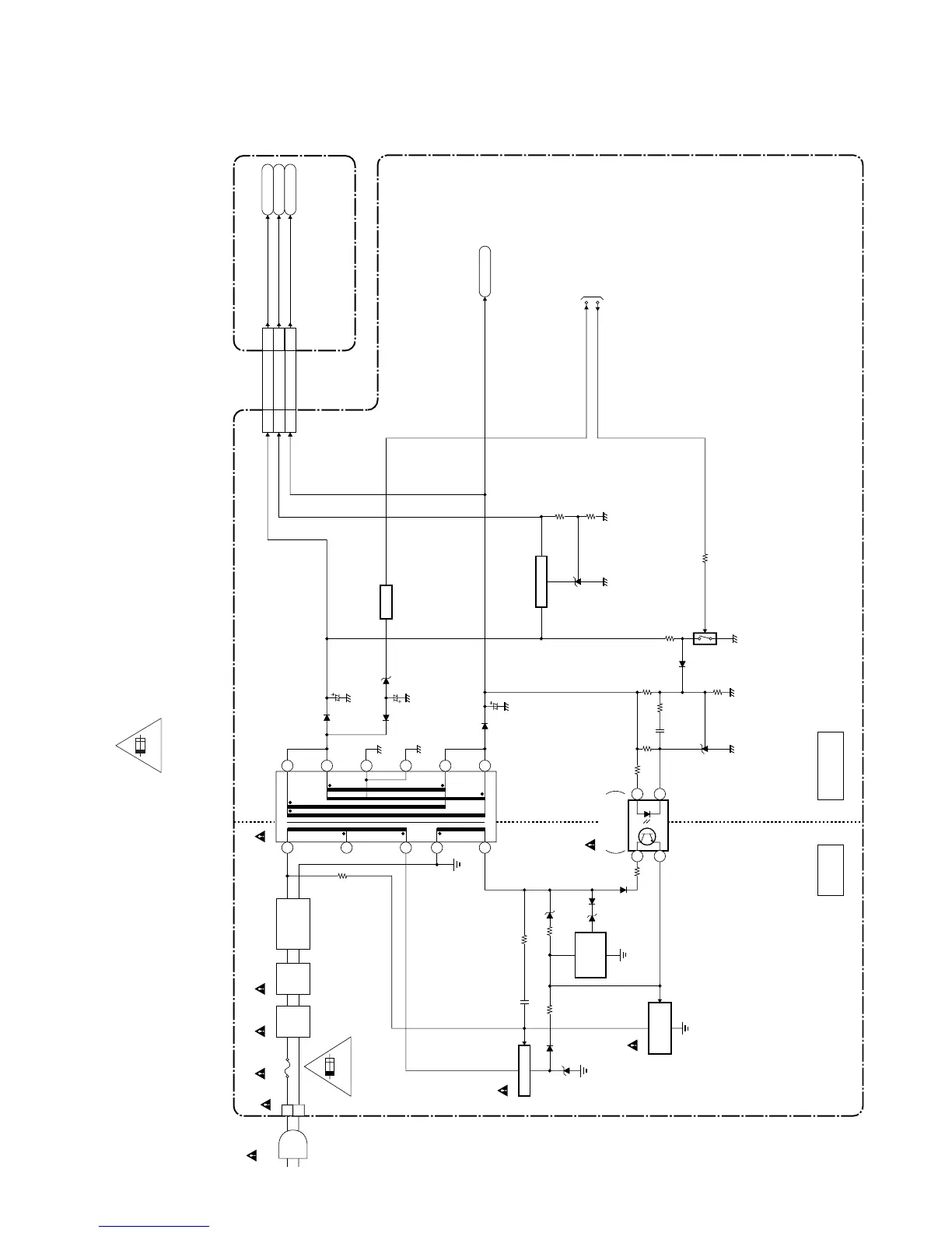
5. Power Supply Block Diagram
HOT COLD
POWER SUPPLY CBA
HOT CIRCUIT. BE CAREFUL.
Q602
SWITCHING
CONTROL
Q621
OVER
VOLTAGE
PROTECT
1
4
3
2
T601
6
LINE
FILTER
L601
CN601
BRIDGE
RECTIFIER
D601- D604
4
5
12
11
10
9
8
7
1
Q601
SWITCHING
CN501
AC601
AC CORD
LINE
FILTER
L602
2.5A 250V
F602
2.5A/250V
Q653
TO
SYSTEM CONTROL
BLOCKDIAGRAM
P-ON-H2
RESET
Q650
RESET
P-ON+21V
8
P-ON+21V
AMP+13V
AL+3.3V
DIGITAL MAIN CBA UNIT
20-23
P-ON+21V20-23
15-18
AMP+13V15-18
AL+3.3V8
CN3601
W
B
ERROR
VOLTAGE DET
IC602
2
Q656, Q658
+3.3V REG.
CAUTION !
Fixed voltage (or Auto voltage selectable) power supply circuit is used in this unit.
If Main Fuse (F602) is blown , check to see that all components in the power supply
circuit are not defective before you connect the AC plug to the AC power supply.
Otherwise it may cause some components in the power supply circuit to fail.
For continued protection against risk of fire,
replace only with same type 2.5A, 250V fuse.
CAUTION ! :
ATTENTION : Utiliser un fusible de rechange de même type de 2.5A, 250V.
2.5A 250V
NOTE:
The voltage for parts in hot circuit is measured using
hot GND as a common terminal.
PL13.11ABLP