Mechanical Instructions
EN 21TPN15.1E LA 4.
2015-Oct-30
back to
div. table
4.4.5 Power Supply Unit (PSU)
Caution: it is mandatory to remount all different screws at their
original position during re-assembly. Failure to do so may result
in damaging the PSU.
1. Gently unplug all connectors from the PSU.
2. Remove all fixation screws from the PSU.
3. The PSU can be taken out of the set now.
4.4.6 Speakers
1. Gently release the tapes that secure the speaker cables.
2. Unplug the speaker connector from the SSB.
3. Take the speakers out.
When defective, replace the both units.
4.4.7 IR/LED Board
1. Remove the stand bracket as described earlier.
2. Gently release the clips that hold the board and take it out
from the bezel.
3. Unplug both the connectors from the IR/LED board.
When defective, replace the whole unit.
4.4.8 LCD Panel
1. Remove the SSB as described earlier.
2. Remove the PSU as described earlier.
3. Remove the keyboard control panel as described earlier.
4. Remove the stand bracket as described earlier.
5. Remove the IR/LED as described earlier.
6. Remove the fixations screws that fix the metal clamps to
the front bezel. Take out those clamps.
7. Remove all other metal parts not belonging to the panel.
8. Lift the LCD Panel from the bezel.
When defective, replace the whole unit.
4.5 Assembly/Panel Removal (only for
32PHT4100/60)
Instructions below apply to the 32PHT4100/60 only.
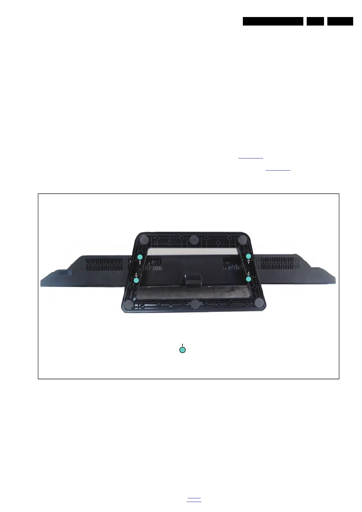
4.5.1 Stand
Refer to Figure 4-21
for details.
1. Remove the fixation screws [1] that secure the stand
bracket. Refer to Figure 4-21
for details.
2. Take the stand bracket out from the set.
Figure 4-21 Stand removal
19791_104.eps
1
1
1
1
1
M4 × 16