Service Modes, Error Codes, and Fault Finding
EN 30 QFU1.1E LA5.
2012-Sep-14
back to
div. table
•Via ComPair.
5.5.3 How to Clear the Error Buffer
Use one of the following methods:
• By activation of the “RESET ERROR BUFFER” command
in the SAM menu.
• If the content of the error buffer has not changed for 50+
hours, it resets automatically.
5.5.4 Error Buffer
In case of non-intermittent faults, clear the error buffer before
starting to repair (before clearing the buffer, write down the
content, as this history can give significant information). This to
ensure that old error codes are no longer present.
If possible, check the entire contents of the error buffer. In
some situations, an error code is only the result of another error
code and not the actual cause.(e.g. a fault in the protection
detection circuitry can also lead to a protection)
There are several mechanisms of error detection:
• Via error bits in the status registers of ICs.
• Via polling on I/O pins going to the standby processor.
• Via sensing of analog values on the standby processor or
the Mips.
• Via a “not acknowledge” of an I
2
C communication.
Take notice that some errors need several minutes before they
start blinking or before they will be logged. So in case of
problems wait 2 minutes from start-up onwards, and then
check if the front LED is blinking or if an error is logged.
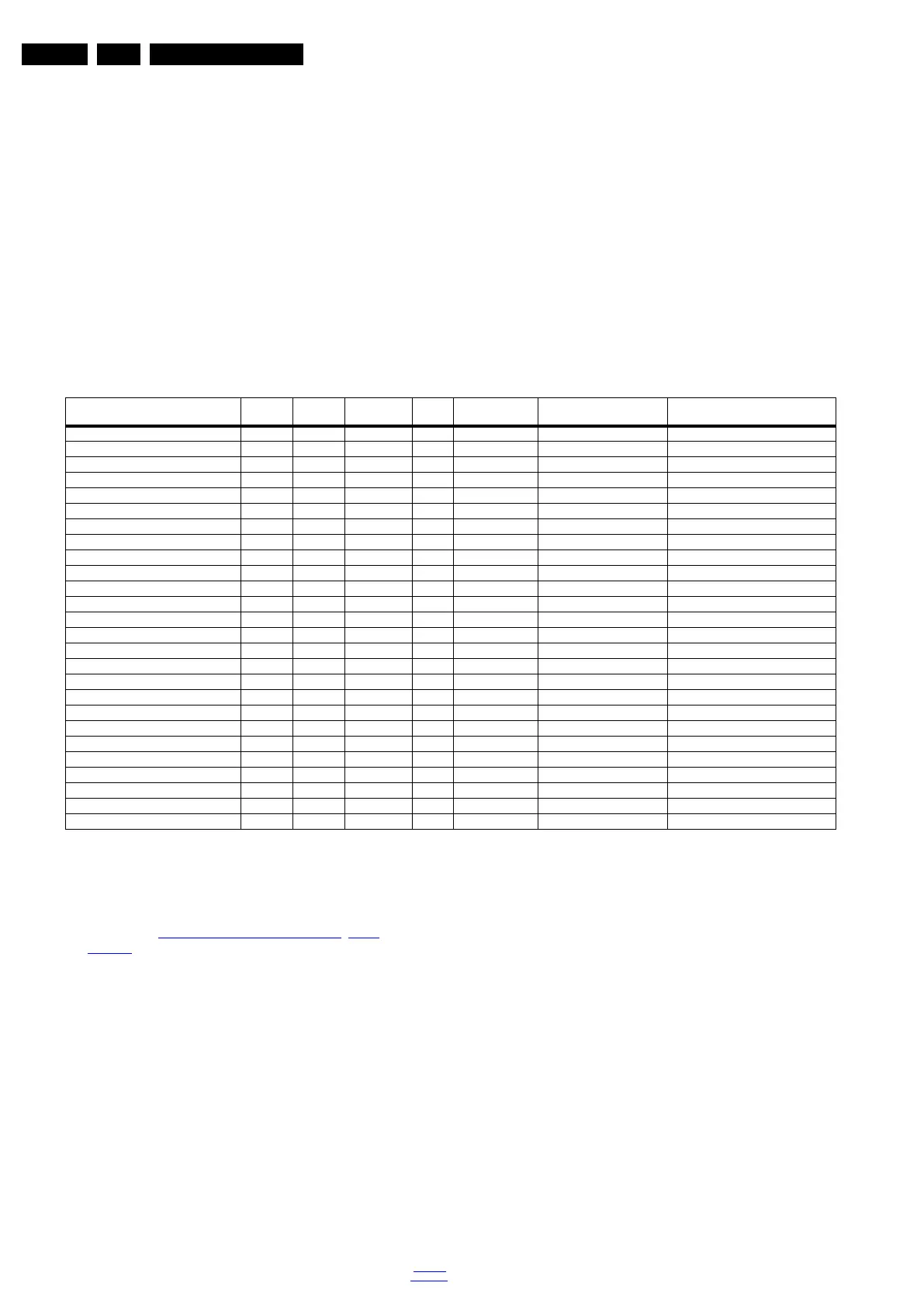
Table 5-2 Error code overview
Extra Info
• Rebooting. When a TV is constantly rebooting due to
internal problems, most of the time no errors will be logged
or blinked. This rebooting can be recognized via a ComPair
interface and Hyperterminal (for Hyperterminal settings,
see section “5.8 Fault Finding and Repair Tips
, 5.8.6
Logging). It’s shown that the loggings which are generated
by the main software keep continuing.
• Error 13 (I
2
C bus M3, SSB + SRF bus blocked). Current
situation: when this error occurs, the TV can reboot due to
the blocked bus. The best way for further diagnosis here, is
to check the logging output.
• Error 14 (I
2
C bus M2, BE bus blocked). Current situation:
when this error occurs. The best way for further diagnosis
here, is to check the logging output.
• Error 18 (I
2
C bus M1, FE bus blocked). Current situation:
when this error occurs. The best way for further diagnosis
here, is to check the logging output.
• Error 15 (Fusion doesn’t boot). Indicates that the main
processor was not able to read his bootscript. This error will
point to a hardware problem around the Fusion (supplies
not OK, Fusion device completely dead, link between Mips
and Stand-by Processor broken, etc...)
Other root causes for this error can be due to hardware
problems regarding the DDR’s and the bootscript reading
from the Fusion device.
• Error 16 (12V). This voltage is made in the power supply
and results in protection (LAYER 1 error = 3) in case of
absence. When SDM (maintain grounding continuously) is
activated we see blinking LED LAYER 2 error = 16.
• Error 17 (Display Supply). Here the status of the “Power
OK” is checked by software, no protection will occur during
failure of the display supply, only error logging. LED
blinking of LAYER 1 error = 3 in CSM, in SDM this gives
LAYER 2 error = 17.
• Error 23 (HDMI mux). When there is no I
2
C
communication towards the HDMI mux after start-up,
LAYER 2 error = 23 will be logged and displayed via the
blinking LED procedure if SDM is switched on.
• Error 24 (I2C switch). When there is no I
2
C
communication towards the I
2
C switch, LAYER 2
error = 24 will be logged and displayed via the blinking LED
procedure when SDM is switched on.
• Error 27 (Channel dec DVB-T2). When there is no I
2
C
communication towards the DVB-T channel decoder,
LAYER 2 error = 27 will be logged and displayed via the
blinking LED procedure if SDM is switched on.
• Error 28 (Channel dec DVB-S2). When there is no I
2
C
communication towards the DVB-S channel decoder,
LAYER 2 error = 28 will be logged and displayed via the
blinking LED procedure if SDM is switched on.
Description Layer 1 Layer 2
Monitored
by
Error/
Prot
Error Buffer/
Blinking LED Device Defective Board
I
2
CM3 (SSB + SRF bus) 2 13 MIPS E BL / EB SSB SSB
I
2
CM2 (BE bus) 2 14 MIPS E BL / EB SSB SSB
I
2
CM1(FE bus) 2 18 MIPS E BL / EB SSB SSB
Fusion doesn’t boot (HW cause) 2 15 Stby µP P BL Fusion SSB
12V 3 16 Stby µP P BL / Supply
Display supply (POK) 3 17 MIPS E EB / Supply
HDMI mux 2 23 MIPS E EB SII9387 SSB
I2C switch 2 24 MIPS E EB PCA9540 SSB
Channel dec DVB-T2 2 27 MIPS E EB CXD2834 SSB
Channel dec DVB-S2 2 28 MIPS E EB STV0903 SSB
Lnb controller 2 31 MIPS E EB LNBH25 SSB
Hybrid Tuner 2 34 MIPS E EB SUT-RE214Z SSB
Main NVM 2 35 MIPS E EB STM24C64 SSB
Tuner DVB-S2 2 36 MIPS E EB STV6110 SSB
Class-D 2 37 MIPS E EB TAS 5731 PHP SSB
FPGAScanBacklight 2 38 MIPS E EB XC6SLX4 SSB
T° sensor SSB/Display 2 42 MIPS E EB LM 75 T° sensor on SSB/Display
Light sensor 6 43 MIPS E EB TSL2571 Set
µP touch control 6 44 MIPS E EB / Set
RF4CE 6 46 MIPS E EB / Set
MIPS doesn’t boot (SW cause) 2 53 Stby µP P BL FUSION SSB
FPGA HDR 5 61 MIPS E BL Xilinx Spartan Display
FPGA Lattice Backlight 5 62 MIPS E BL Lattice Display
TCON µP (SHARP) 7 54 MIPS E BL / Display
TCON ASIC (SHARP) 7 55 MIPS E BL / Display
VCON cal (SHARP) 7 56 MIPS E BL / Display
 Loading...