22
TC8600 and TC8800 Video Inputs
The TC8601 and TC8801 main bays have only 96
direct BNC connectors available for video input.
Cameras above 96 require the use of the TC8808
Video Interconnect ("Patch") Panel. Each patch
panel provides 32 additional BNCs for video input.
Patch panels are connected to the rear of the main
bay using the supplied ribbon cables. Each cable can
carry video for up to 16 cameras. Two cables can be
attached to each patch panel to support up to 32
cameras per panel. Each ribbon cable should be
attached to the appropriate "VIDEO" connector on
the rear of the main bay. The ribbon cable
connectors contain a small “key” protrusion
formed into one side of the connector to assure
proper placement into the mating connectors. Be
careful not to force the cables into the mating
connectors backwards. For example, the two
ribbon cables from the first patch panel (supporting
the thirty-two cameras 97 through 128) should be
attached to the main bay connectors labeled "VIDEO
97-112" and "VIDEO 113-128." Extra connectors are
provided on the main bay for "looping" purposes. If
camera inputs are not being looped to other
equipment, only one connector for each range of
cameras (e.g., "VIDEO 97-112") needs to be
connected.
The TC8600 system is supplied with one TC8808
(patch panel plus two TC8809 ribbon cables). This
should be installed on the rear of the racking
equipment to permit immediate or future connections
of camera inputs 97 through 128.
KEYBOARD
VIDEO IN
1
3
5
7
2
4
6
8
CONSOLE
ALARM
PRINTER
SDA
COMM PORT 1
COMM PORT 2
1
3
VIDEO
OUT
2
4
9
1011
12
17181920
25
2627
28
33
3435
36
41
4243
44
49505152
57
5860
65
66
6768
73
74
7576
81
828384
89
90
9293
94
96
85
868788
77
78
7980
69
70
7172
61
6264
53545556
45
4647
48
37
3839
40
29
3031
32
21222324
13
1415
16
5
67
8
1
SYNC
IN
6
7
8
9
10
11
12
5
4
3
2
16
15
14
13
LOOP 1-16
LOOP 17-32
LOOP 33-48
LOOP 49-64
LOOP 65-80
LOOP 81-96
INPUT 97-112
LOOP 97-112
INPUT 113-128
LOOP 113-128
59
9195
63
16
32 31 30 29
15 14 13
28 27 26 25
12 11 10 9
24 23 22 21 20 19 18
8 7 6 5 4 3 2
17
1
TC8601 R EAR PAN EL
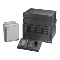
Camera Input 97
Camera Input 98
Upper TC8809 Cable
TC8808 Interconnect Panel
Lower TC8809 Cable
S9506053AE
Typical Use of TC8808 Video Interconnect Panel
The TC8800 system is supplied with TC8808s only if
the number of TC8821 Video Input Modules ordered
requires their use. Install any supplied TC8808 patch
panels on the rear of the racking equipment. Note
that additional TC8821 Video Input Modules ordered
in the future may also require the use of TC8808
patch panels. Order appropriate quantities at the
time the TC8821 Video Input Modules are ordered.
Termination Practices
Video from every camera should be "terminated"
with a 75 ohm resistance. Each video line should be
terminated exactly once. If video from a given
camera is going to several different devices, only the
last piece of equipment on the video line should be
terminated. See the section below for special
termination instructions when using a monitor
expansion bay. Allegiant systems terminate their
video inputs as follows:
TC8500 Terminations
Each TC8521VOM Video Input Module has resistors
that terminate the video lines. If the user wishes that
a video input be non-terminated so it may be used as
a looping input, the VIM card must be modified. This
modification can be done by the installer, as long as
standard handling precautions are observed. Only
competent technicians should attempt this
procedure. For each video input that should be non-
terminated, a resistor must be removed from the
appropriate VIM card. These resistors are labeled as
follows:
input 1 - R1 input 5 - R93
input 2 - R96 input 6 - R95
input 3 - R43 input 7 - R92
input 4 - R91 input 8 - R94
BNC "T" connectors must then be used to connect
looping system cameras to the non-terminated inputs
on the rear of the main CPU bay. A short piece of
coax is recommended to connect the "T" to the bay.
TC8600 or TC8800 Terminations
Each VIM card for a TC8600 or TC8800 system has
DIP switches for selecting the termination of each
individual video line. To terminate an input line,
make sure that the appropriate DIP switch on the
VIM card is ON. If non-terminated operation is
required for looping purposes, turn the switch OFF.
If looping video inputs are desired, the TC8600 and
TC8800 systems may utilize the TC8808 patch panel
kit. Both bays provide video looping connections
which interface to the TC8808 patch panel using
coax type ribbon cables supplied with the patch
panel. Each TC8808 provides looping capability for
up to 32 video inputs.
Just like camera inputs, monitor outputs on the
Allegiant system are designed to be terminated.
Each monitor output expects to be connected to a 75
ohm load. This is the regular load typically provided
by a normal monitor. If a monitor output line is
"looped" through several monitors or other
equipment, the system installer should make sure
that only the last unit on the line is terminated.
TC8802 Expansion Bay
Connections
 Loading...