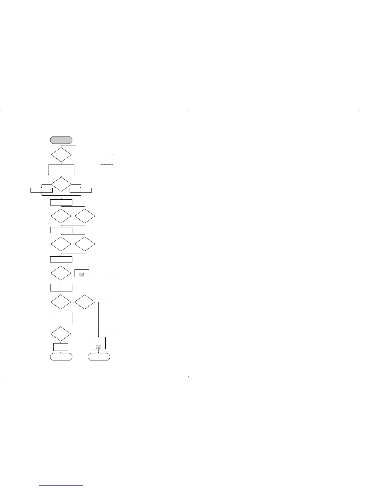
CD STARTUP PROCEDURE
4-3 4-3
PCS 99 155
Abbreviations and Pin-descriptions of CD ICs
SERVO PROCESSOR M62475FP
Pin Name Direction Description
1-3
A, B, C
Diode array
Servo processor
Current input (central photo diode signal input)
4-5
E, F
Diode array
Servo processor
Current input (satellite photo diode signal input)
6 SGT
Servo processor
Track error ampl. Input
Signal generator output to track servo, sends 1700Hz for adjustment procedure
7 TE - - Inverting input of track error amplifier
8 TEGain - Gain control pin of track error amplifier
9 TG1 - Track Gain 1 - switch: controls the gain of the track servo amplifier
10 TE out - Track Error amplifier output
11 TC/Shock - Track Cross/Shock detector input
12 TS + - Non inverting input of track servo amplifier
13 TG2 not connected Track Gain 2 - switch: controls the gain of the track servo amplifier
14 TS - - Inverting input of side servo amplifier
15 TS out
Servo processor
Servo driver
Output of track servo amplifier
16 SS + - Non inverting input of slide servo amplifier
17 SS - - Inverting input of slide servo amplifier
18 Slide out
Servo processor
Motor driver
Output of slide servo amplifier
19 DET. FILTER -
Pin for connection of DETection FILter capacitor of ADJUST LOGIC
20 BIAS
Servo processor
external electronic
Reference Voltage output Vcc/2 of internal BIAS-generator
21 GND - Ground connection pin (negative supply)
22 MLA/DIS
Servo processor
Serial interface Microprocessor Latch control/DIScharge control for adjustment
23 JP1/SG
Servo processor
Serial interface Jump control line/Signal Generator input line for adjustment
24 MCK
Servo processor
Serial interface Clock input line
25 MSD
Servo processor
Serial interface Data input line
26 D
out
Servo processor
p
Serial interface Data output line
27 C
LPF
-
Pin for connection of Low Pass Filter capacitor of ADJUST LOGIC
28 I
REF
- Reference current input
29 V
CC
- Positive supply connection pin (4V - 5.5V)
30 FS
OUT
Servo processor
Servo driver
Output of focus servo amplifier
31 FS - - Inverting input of focus serco amplifier
32 FEGain - Gain control pin of focus error amplifier
33 FE - - Inverting input of focus error amplifier
34 SGF
Servo processor
Focus error ampl. Input
Signal generator output to focus servo, sends 1300Hz for adjustment procedure
35 C
FSR
- Charge capacitor for Focus Search triangle-generator
36 ALPC + - Non inverting input of Automatic Laser Power amplifier
37 ALPC - - Inverting input of Automatic Laser Power Control amplifier
38 ALPC
OUT
Servo processor
Laser driver
Output of Automatic Laser Power Control amplifier
39 MRC - Connection pin for capacitor of Mirror detector
40 HF
Servo processor
Decoder
Output of HF amplifier
41 HFI - Inverting input of HF amplifier
42 ABC - Sum output of amplified A, B and C input (central photo diode signal input)
to external ac-coupling capacitor
SERVO PROCESSOR M65824FP
Pin Name Direction Description
1 Anal. V
SS
- Analog system ground
2 ADJCLK not connected Clock output for servo adjustment; f=88.2kHz
3 LOCK not connected Lock monitor / low disc rotation output
4 CKSEL - System clock selection. Low=8.4672MHz, high=16.9344MHz
5 RESET
Signal processor
System reset (low level = active)
6 C423
Signal processor
p
4.2336MHz clock output
7 C846 not connected 8.4672MHz clock output
8 XI
X-Tal
Signal processor
Crystal oscillator input
9 DVSS - Digital system ground
10 XO
Signal processor
X-Tal
Crystal oscillator output
11 TEST - Normal / Test selection input. Testmode = high
12 SBCO not connected Subcode serial output
13 SCCK - Shift clock input for subcode data read
14 SYCLK not connected Frame lock status output. Lock = high
15 EFFK not connected EFM frame clock output. Duty = 50%
16 KILLB not connected Digital silence mute output. Digital zero = low
17 EST1 not connected Error monitor output 1
18 EST2 not connected Error monitor output 2
19 HF
Servo processor
Signal processor
HF signal input
20 TLC - Slice level control signal output
21 LPF - PLL loop filter
22
Dig. V
DD
- Digital interface power supply
23 DSPS - Digital system power supply
24 SBQS not connected Interrupt signal to read out subcode Q data. Read = low
25 CRCF not connected Subcode Q-channel Cyclic Redundance Check Flag output. CRC o.k. = high level
26 SCAND not connected Subcode sync signal detection. Sync = high
27 PWM
Signal processor
Motor driver
Disc motor driving (Pluse Width Modulation) output
28 DVDD2 - Digital interface power supply 2
29 DVSS2 - Digital system ground 2
30 MCK
p interface shift Clock input
31 MSD
p interface Serial Data I/O line
32 MLAB
p interface Latch clock input (internal 22k pull up resistor)
33 EXP1
Signal processor
Versatile input pin (internal 4.7k pull up resistor)
34 EXP2
Signal processor
Versatile input pin (internal 4.7k pull up resistor)
35 CGREF
Signal processor
Charge-pump for LPF reference current input
36 AMPREF not connected Op-amp for LPF reference voltage setting
37 LOUT/DO
Signal processor
Audio signal output (left channel) / Ext. DAC mode: Audio serial data output
38 LNEG not connected Charge pump output (left channel) / Ext.DAC mode: Wordclock output
39 ROUT/DSCK
Signal processor
Audio signal output (right channel) / Ext. DAC mode: Data shift clock output
40 RNEG/LRCK
Signal processor
Charge pump output (right channel) / Ext.DAC mode: L/R clock output
41 IREF - Current reference
42 Anal. V
DD
- Analog system power supply
N
Y
N
N
N
N
N
Y
CD switched on
(mode switch)
+A(CD)
supplied to
CD part?
Decoder delivers CLOCK -
frequ. 4.23MHz to µP.
µP-RESET line Æ high
µP init. Decoder 7801.
inner switch
closed?
4s time-out over?
0,2s time-out over?
inner switch open?
Laser on
Disc motor 100ms on
FOCUS search on
focus found? 3s time-out over?
N
startup proc.
stopped,
display shows
µP initializes Decoder
and Servo IC:
-start turntable
-adj. track bal. and gain
-read subcode (TOC)
TOC
found?
display shows
max. trackno.
Y
Y
Y Y
N
Y Y
Remark: To check focus servo, slide servo, track servo and turntable
use service test program
- Battery empty?
- check +A,
- mode switch o.k.?
check: - Motor control pin 27 of Decoder 7801 and
Disc Motor driver 7805
- HF Signal by using service testprogram
check: - Laser light on ?
Check pin 38 of 7803 and LASER CONTROL circuit
- Focus Servo
HIGHLOW
Level on
pin23
(CD-RESET)
after 100µs?
Init. 7801 for ext. DAC Init. 7801 for int. DAC
BEGIN
µP moves slide inside
(4s time-out starts)
µP moves slide outside
(0,2s time-out starts)
STOP MODE STARTUP FAILED
CDstartup EVA, 080997
slide off
N
Y
check: - door switch
Door closed?
Display shows
check: - +A(CD), +B(CD), +LASER, +M,
- time constant of reset circuit
- Pin 32 of µP 7800 HIGH ?
- Pin 30 of µP 7800, if 4.23 MHz o.k.
 Loading...