EasyManua.ls Logo

Philips AZ2030 User Manual

Philips AZ2030
34 pages
To Next Page IconTo Next Page
Page #1 background imageLoading...
Page #1 background image
CLASS 1
LASER PRODUCT
GB
3140 785 22580Published by SS 0115 Service Audio
or otherwise without the prior permission of Philips.
system or transmitted, in any form or by any means, electronic, mechanical, photocopying,
All rights reserved. No part of this publication may be reproduced, stored in a retrieval
Copyright 1995 Philips Consumer Electroncis B.V. Eindhoven, The Netherlands
be used.
condition and that parts which are identical with those specified
Safety regulations require that the set be restored to its original
C
PCS 107 271
Printed in The Netherlands Copyright reserved Subject to modification
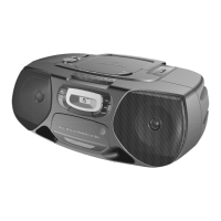
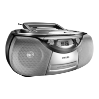
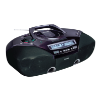
CD Stereo Radio Recorder
TABLE OF CONTENTS
chapter
Handling chip components and safety 1 - 1
AZ2030
AZ2035
.............................
Technical Specification & Service Tools 2 - 1
..........................
Service Measurement 2 - 2
..................................................
Connections & Controls
3 - 1
................................................
Disassembly Diagram 4 - 1
...................................................
Instructions for use
3 - 2 to 3 - 6
.................................................
CD Service Test Program 4 - 2 to 4 - 3
........................................
Block Diagram
5 - 1
.............................................................
Wiring Diagram 5 - 2
...........................................................
circuit diagram
6 - 1
.......................................................
FRONT BOARD
layout diagram
6 - 2
.......................................................
circuit diagram
7 - 1
.......................................................
AF & POWER BOARD
layout diagram
7 - 2
.......................................................
chapter
circuit diagram
8 - 1
.......................................................
FEATURE BOARD
layout diagram
8 - 1
.......................................................
circuit diagram
9 - 1
.......................................................
TUNER BOARD
layout diagram 9 - 2
.......................................................
circuit diagram 10 - 1
.......................................................
REOCRDER BOARD
layout diagram 10 - 2
.......................................................
circuit diagram
11 - 2
.......................................................
CD MODULE
layout diagram 11 - 1
.......................................................
cabinet
12 - 1
.................................................................
EXPLODED VIEWS DIAGRAM
tape deck
12 - 2
............................................................
Mechanical partslist
12 - 2
.....................................................
Electrical partslist
13 - 1 to 13 - 5
...............................................
all versions

Other manuals for Philips AZ2030

Question and Answer IconNeed help?

Do you have a question about the Philips AZ2030 and is the answer not in the manual?

Philips AZ2030 Specifications

General IconGeneral
BrandPhilips
ModelAZ2030
CategoryRecording Equipment
LanguageEnglish

Summary

Handling Chip Components

Dismounting Procedures

Steps for removing components.

Mounting Procedures

Steps for installing components.

Handling Precautions

Safety and best practices for handling components.

ESD Precautions

Specific warnings about electrostatic discharge.

Laser Safety Warning

Warning about invisible laser radiation when open.

Technical Specifications

Service Measurements

FM Tuner Measurement Setup

Setup for measuring FM tuner performance.

AM Tuner Measurement Setup

Setup for measuring AM tuner performance.

CD Measurement Setup

Setup for measuring CD player performance.

Recorder Measurement Setup

Setup for measuring tape recorder performance.

Instruction for Use

Radio Tuning Operations

Tuning grid, station tuning, programming, presets.

CD Play Modes (Shuffle/Repeat)

How to use shuffle and repeat functions.

Programming CD Tracks

How to set up a custom track sequence.

Cassette Playback and Recording

Instructions for cassette playback and recording.

Recording from Radio

How to record radio broadcasts onto tape.

Tape Deck Maintenance

Procedures for cleaning tape deck parts.

Troubleshooting Common Issues

Solutions for typical problems and errors.

Disassembly Diagram

Top Cabinet and Front Panel Removal

Steps to remove top cabinet and front assembly.

Tape Deck and Front Board Removal

Steps to remove tape deck and front board.

CD Service Test Program

Entering CD Test Mode

How to access the CD service test program.

CD Test Functions

Description of display, servo, and motor tests.

Tuner Test Program

Entering Tuner Test Mode

How to access the tuner service test program.

Tuner Test Parameters

Description of test frequencies and settings.

CD IC Abbreviations and Pin Descriptions

Servo Processor SAA7325H Details

Pin details for the SAA7325H servo processor.

Other CD IC Pin Descriptions

Pin details for other CD related integrated circuits.

Block Diagram

Front Board - Circuit Diagram

AF & Power Board - Circuit Diagram

Feature Board - Circuit Diagram

Tuner Board ECO6 - Circuit Diagram

FM and AM RF Stages Circuitry

Circuitry for FM and AM radio frequency stages.

Recorder Board - Circuit Diagram

Recorder Board - Layout Diagram

Cassette Adjustment Procedures

Steps for adjusting tape deck parameters.

CD99 DA11 - Circuit Diagram

Exploded View Diagram - Tape Deck

Electrical Partslist - CD99 DA11

Related product manuals