Service Modes, Error Codes, and Fault Finding
EN 16 BP2.2U, BP2.3U5.
How to Exit CSM
Press any key on the RC-transmitter (with exception of the
“CHANNEL +/-”, “VOLUME”, “MUTE” and digit (0-9) keys).
5.3 Stepwise Start-up
The stepwise start-up method, as known from FTL/FTP sets is
not valid any more. The situation for this chassis is as follows:
when the TV is in a protection state detected via the Stand-by
Processor (and thus blinking an error) and SDM is activated via
shortcutting the pins on the SSB, the TV starts up until it
reaches the situation just before protection. So, this is a kind of
automatic stepwise start-up. In combination with the start-up
diagrams below, you can see which supplies are present at a
certain moment.
Important to know here is, that if e.g. the 3V3 detection fails
(and thus error 11 is blinking) and the TV is restarted via SDM,
the Stand-by Processor will enable the 3V3, but will not go to
protection now. The TV will stay in this situation until it is reset
(Mains/AC Power supply interrupted).
The abbreviations “SP” and “MP” in the figures stand for:
• SP: protection or error detected by the Stand-by
Processor.
• MP: protection or error detected by the VIPER Main
Processor.
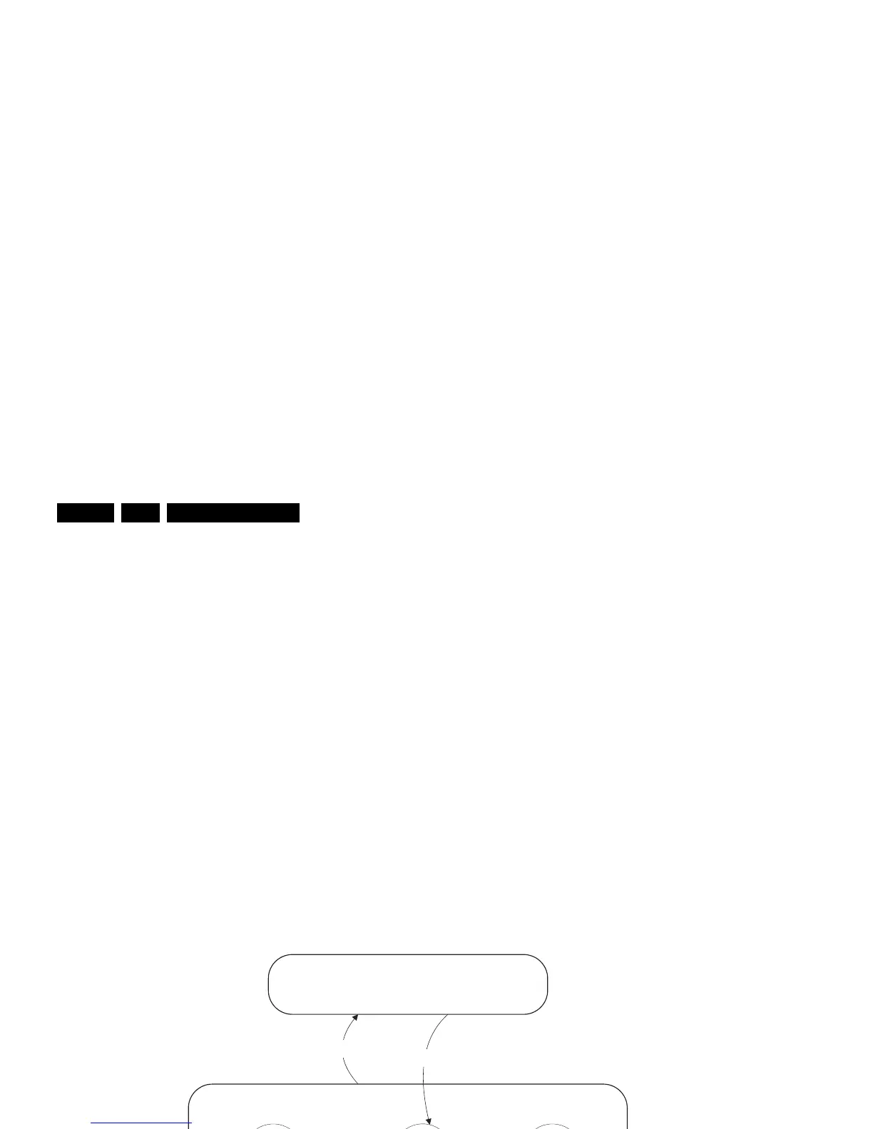
Figure 5-2 Transition diagram
On
Active
Semi
Stand-by
Stand-by
(Off St-by)
Off
Mains
“on”
Mains
“off”
GoToProtection
- WakeUp requested
- Acquisition needed
- No data Acquisition required
and no POD present
- St-by requested
- Tact SW pushed
WakeUp
requested
Protection
WakeUp
requested
GoToProtection
POD
Stand-by
No data Acquisition
required and
POD present
d
GoToProtection
- WakeUp requested
- Acquisition needed
- Tact SW pushed
- POD Card remove
- Tact SW pushed
F_15400_095.eps
300505