.
\ ,.
, @ CISASSEMBL Y - Slide adjusting jig 4822 402 60245 over the
! capstan while pressure roller 68 is slightly pulled
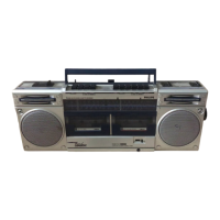
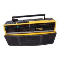
\..., Cabinet (refer to Fig. 5) back.
Remove battery compartment lid 471, take out 7 - The jig mu~t ~e.sli? ove~ the capstan to such.an
~ screws and remove back cover 468 (be attentive to extent that It IS In Iine wlth the er~se head guIdes.
. . - The R/P-head must ncw be so adJusted that the
wlrlng). jig slides exactly between the tape guides of the
Removal of printed-circuit board (PCB-A) two heads.
\ / - Prise off the knobs 404, 442, 444.
- Take out the three screws to enable PCB-A and The friction force can be measured with the friction
chassis 567 to be withdrawn trom the cabinet. measurement cassette 4822 395 30054 (811/CTM) in
position "start"
I Removal of printed-circuit board (PCB-C) Th . .
I t b- Take out the 3 x 10 screw (S). e measurln.g va ue mus e: .. ...
- PCB-C and panel 571 may ncw be withdrawn - Take-up slde 40-60 gcm. Permlsslble variation In
trom the cabinet. (Be attentive to wiring). bcetweten t~dese4 v8alues 10 gcm.
- Dun er SI e - gcm.
~ Removal of printed-circuit board (PCB-B) and tape - The friction force is determined by the sloping up
transport unit sides and the flat springs, Figs. 4 a and b.
- Take out the 3 countersunk screws. - The force is adjustable by catching the flat spring
'-" - PCB-B (+ tape transport unit) may ncw be with- behind another stud.
drawn af ter having unplugged the wiring.
Ch k . th I d th t d . t tec Ing e ace-up an e caps an a Jus men
Removal of printed-circuit board (PCB-D) - Recorder in the position "playback" with the
'---"' - Remove all of the rotary and slide knobs, then mirror cassette inserted.
take out 2 screws (from bottom side) and with- - Wh en the tape at the capstan moves upwards or
(" draw PCB-D trom the cabinet. (When reassem- downwards, adjust the capstan to be
bling, be attentive to the springs 558). perpendicular by means of Bon the flywheel pivot
'-" Removal of cassette lid holder 426 bearing (Fig. 1). .
- Open cassette lid and slightly lift the LH pivot - The tape sh.ould be straight and smooth between
I .
t f tt I.d h Id 426 the tape guIdes and along the capstan.
poln 0 casse e loer.
S II d ,. f th . tt . '
bi'- ma evlatlons rom IS pa ern are permlssl e,
Removal of handle because they do not have an effect tor normal
- The handle may be removed af ter having lifted the cassettes.
caps 417. Adjusting the flywheel play
"-"
T d k F. 4 - The flywheel play should be noticeable, but may
" ape ec Ig.
, not exceed 0.3 mmo
Remove pressure roller 68 Adjust by turning A (Fig. 1).
\../ Remove plug 67, compression spring 69 and torsion
" spring 508. ELECTRICAL MEASUREMENTS ANC
Remove head support bracket 52 ACJUSTMENTS (see Fig. 7)
\ ' Remove tension spring 54. N .
Remove pressure roller 68. otes: ..
B ushin the head su port bracket slightly back- - Prior to a~y measurement or adJ~stment wlth the
y Pd .t 9 b dp tape running, heads and tape guIdes should be
war s I can eremove.
. . degaussed and cleaned.
Remark: Mlnd the 2 bal Is 58, they ncw Iie loose.
Th t d d.
t t I t d t\ / - e measuremen s an a Jus men s are re a e 0
Remove buttons 59,62,63,64,66,121, Fig. 4 the left-hand channel.
Remove pressure roller 68. The corresponding test points and adjusting
Remove head support bracket 52. elements tor the right-hand chann~1 are given in
""-" Remove locking bracket 53. brackets.) . .,
By pressing the locking tag of the relevant button - The voltages have been measured relative to
\ slightly inwards, this button is released and can be earth.
pushed trom the chassis.
When doing this, mind pressure spring 61. Required test equipment and test cassettes
Remove switch SK-K (111) - AF generator.
\ The switch consists of 2 separate flat springs, - AC-millivoltmeter.
directly fitted in the chassis. - Wo.w-and-flutter-meter.
Unsolder the two connecting wires and properly - Unlversal test cassette SBC126Cr 4822 379 30038.
L clean the soldering spots on the switch. .
Remove circlip 87 so that reel disc 92 can be pushed Remarks (see Fig. 7)
upwards. *a The wow-and-flutter value should not exceed
Remove lever 509 and unfasten the connection 0.3%.
~ between brackets 91 and 93.
Unbend the locking tags of switch springs 111. *b Disable the bias by connecting the base of 6297 to
From the upper side the springs can be removed trom ground.
"-" the chassis. *c If the accuracy requirements are less stringent a
high-quality chromium cassette may be used as
ACJUSTMENTS ANC CHECKS an alternative,
. . . *d The mV-meter should read 580 mV. If not, reduce
"'-' Helght of the recordlng/playback head K1, Fig. 4 the AF-s.ignal (bias disabled) by ~s many dB's as
- Switch off the supply voltage, the reading was toa low or toa high by means of
'- - Remove cover 403 (see Fig. 5). R3363 (3364),
V *e Restore the bias, make a recording and play it
back.
, CS 80 180
\ /
 Loading...