Do you have a question about the Philips IntelliVue and is the answer not in the manual?
Overview map of potential problem areas in the telemetry system.
Indicates a patient lead has fallen off or a fault within the transmitter.
Transmitter entered RF auto-shutoff due to prolonged LEADS OFF condition.
Transmitter detected an incorrect wire leadset or EASI/standard configuration mismatch.
Transmitter's phase-lock loop is no longer functioning.
Covers ECG equip malfunction, transmitter malfunction, and arrhythmia requirement issues.
Covers 'Battery Weak' and 'Replace Battery' messages and related troubleshooting.
Addresses SpO2 circuit malfunctions in the transmitter.
Covers erratic SpO2 readings due to transducer or positioning issues.
Addresses interference affecting SpO2 measurements from ambient light or equipment.
Covers issues when the SpO2 transducer is disconnected or faulty.
Groups 'Noisy Signal', 'Non-Pulsatile', and 'Transducer Malfunction' SpO2 issues.
Covers 'Power On/Off' button issues and 'No Data From Bed' INOP.
Explains receiver board location diagrams and LED behavior for troubleshooting.
Shows LED patterns for abnormal bootstrap sequence troubleshooting.
Covers 'No Receiver' and 'Receiver Malf' INOPs related to receiver modules.
Addresses issues when the transmitter button press does not yield the desired result.
Covers 'INVALID SIGNAL E01INOP' and related interference problems.
Addresses frequent dropouts and weak signals on single or multiple channels.
Covers interference causes like heterodyning and broadband noise.
Explains how to interpret RF History Strip recordings for signal strength and invalid data.
Table correlating RSSI counts to power levels for receiver calibration.
Guidelines for expected signal strength, dropouts, and noise floor.
Helpful hints for examining RF history strips to identify signal issues.
Explanation of the aligned notation used on RF History Strip recordings.
Lists exchange and new part numbers for M2601A transmitters.
Lists more transmitter parts including battery accessories.
Lists case assemblies, screw kits, and grounding strips for transmitters.
Lists PCBs, front end assembly, and connector plugs for transmitters.
Lists leadsets, combiners, and SpO2 transducers for transmitters.
Lists various SpO2 transducers and adapter cables for transmitters.
Lists tools, testboxes, and firmware disks for transmitters.
Lists parts for receiver modules, including gaskets and shield assemblies.
Lists receiver boards, labels, and tools for receiver modules.
Lists components for receiver mainframes like fans, boards, power supplies, and cables.
Lists power cords, fuses, mounting hardware, and screws for receiver mainframes.
Lists tools and software/firmware for receiver mainframes.
Lists components for the analog output option, including cables and modules.
Lists monitor cables, firmware, and faceplates for the analog output option.
Lists parts for M1408A active antenna/combiner systems.
Lists parts for M1406A line amplifiers.
Lists parts for M1407A multiple unit power supplies.
Lists splitters, combiners, and spacers for M1413/14/15B antenna systems.
Lists attenuators, filters, capacitors, terminators, and cables for antenna systems.
Lists attenuators, filters, capacitors, terminators, and cables for antenna systems.
Lists various antenna cables for M2613/14/15A systems.
Lists tools and attenuators for antenna systems.
Lists parts for M2616A frequency converter assemblies and power modules.
Lists service kits, guides, and notes included in Release C documentation.
Lists Philips Telemetry System Instructions for Use in various languages.
Lists user documentation in additional languages and "What's New" sections.
Lists application notes for EASI, SpO2, and Arrhythmia monitoring.
| Battery Backup | Yes |
|---|---|
| Power Supply | 100-240 VAC, 50/60 Hz |
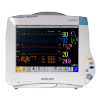
| Category | Patient Monitor |
| Manufacturer | Philips |
| Model | IntelliVue |
| Display Size | 12.1 inches |
| Display Type | TFT LCD |
| ECG | Yes |
| SpO2 | Yes |
| NIBP | Yes |
| Temperature | Yes |
| Respiration | Yes |
| Invasive Blood Pressure | Yes |
| Cardiac Output | Yes |
| EtCO2 | Yes |
| Connectivity | Ethernet, USB, Serial |
| Networking | Yes |


 Loading...