Troubleshooting Overview
2
Troubleshooting Overview
Troubleshooting Map
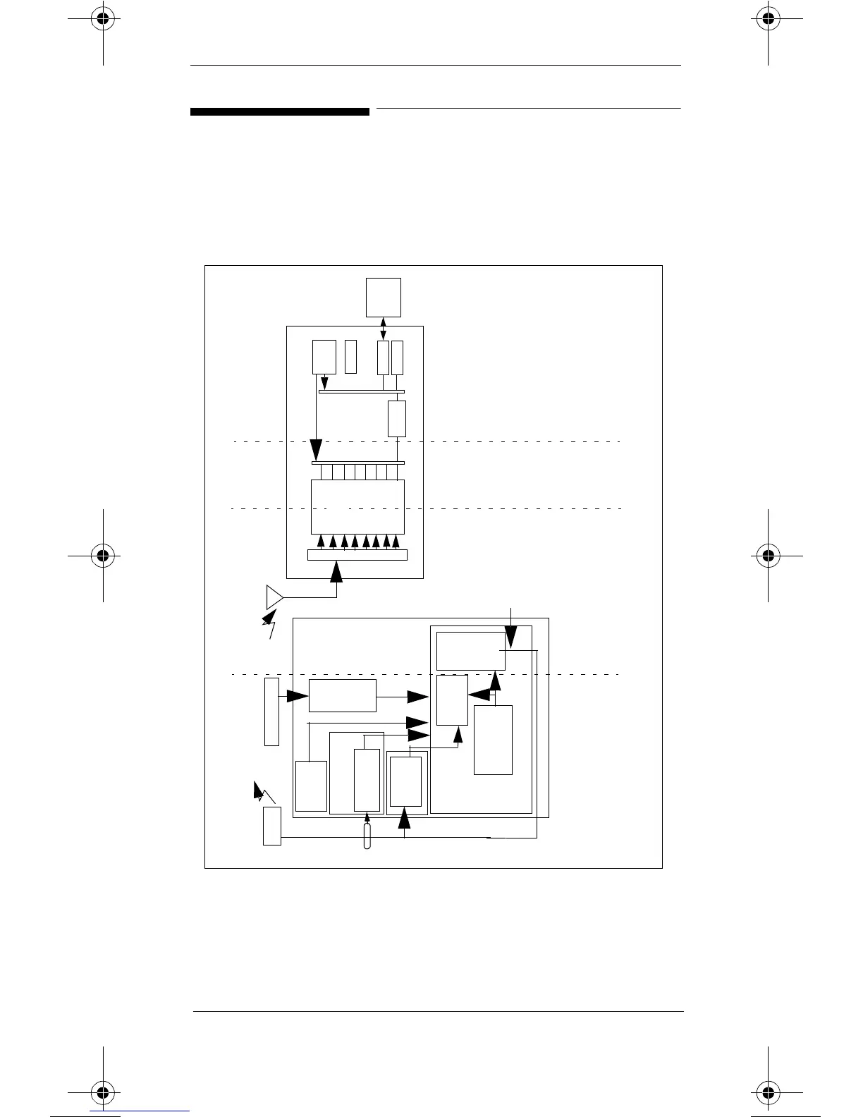
Figure 1 provides an overview map of areas of the
Telemetry System where problems can occur.
Figure 1 Telemetry System Troubleshooting Map
M2601A
Transmitter
Patient
Button
3/5 Leadset
Switch
Main PCB
ECG PCB
Digital
Section
Power Supply
and Battery
RF
Sec-
tion
Leadset
SpO
2
PCB
Transducer
Transmits
Via Leadset
Receiver
Module
(up to 8)
Power
Supply
Digital Backplane
CPC
SDN
Utility
Rack
Interface
Receiver Backplane
Central
Station
RF
Section
Digital
Section
Antenna Distribution Board
- Application
- Transmitter non-RF
- LEADS OFF
- BATTERY INOPs
-ECG EQUIP MALF INOP
-TRANSMITTER MALF INOP
-SpO
2
INOPs
TRANSMITTER OFF
INVALID LEADSET
ARRHY REQUIRED
RF
- No Signal
- Tel Cannot Analyze
- Weak Signal
- Invalid Signal E01
- Interference
Receiver
Non-RF
- Receiver Mainframe
- System
- No Receiver
- Receiver
Malfunction
- NO DATA FROM BED
-No Power at Receiver Main-
frame
M2604A Receiver Mainframe
Front End Assembly
quickref.fm Page 2 Wednesday, June 5, 2002 3:08 PM