CABLE
SATELLITE
ANTENNA
VIDEO
IN
OUT
IN
AUDIO
L
AUDIO
R
VIDEO
OUT
AUDIO
L
AUDIO
R
VHF/UHF
RF IN
VHF/UHF
RF OUT
S-VIDEO
B
C
E
D
Back of a Cable Box
or Satellite Receiver
(Example only)
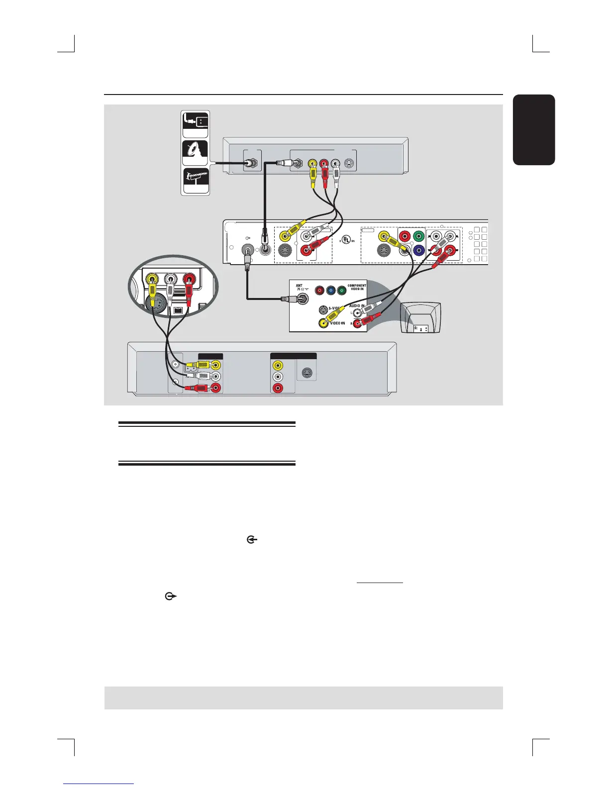
Connecting to a VCR and
Cable Box/Satellite Receiver
A
Connect the Antenna/Cable TV signal to
the antenna input (RF IN) jack on the
Cable Box/Satellite Receiver.
B
Use the supplied RF coaxial cable to
connect the ANTENNA-IN jack on
the recorder to the RF OUT jack on the
Cable Box/ Satellite Receiver.
C
Use a RF coaxial cable to connect the
TV-OUT jack on the recorder to
the antenna input jack on your TV (VHF/
UHF RF IN.)
D
Use the supplied audio/video cables to
connect the VIDEO/AUDIO INPUT
jacks on the recorder to the matching
VIDEO/AUDIO output jacks on the
Cable Box/ Satellite Receiver.
E
Use the audio/video cables to connect
the VIDEO/AUDIO OUTPUT on the
recorder to the matching VIDEO/AUDIO
input jacks on the TV.
F
Use another set of audio/video cables to
connect the CAM1 /L-AUDIO-R jacks
on the front panel of the recorder to the
to the matching VIDEO/AUDIO (yellow/
red/ white) output jacks on the VCR.
TIPS: Before making or changing any connections, make sure that all the devices are disconnected
from the power outlet.
F
Back of a VCR
(Example only)
Front Panel of
recorder