CABLE
SATELLITE
ANTENNA
A
B
C
Back of a Cable
Box or Satellite
Receiver (Example
only)
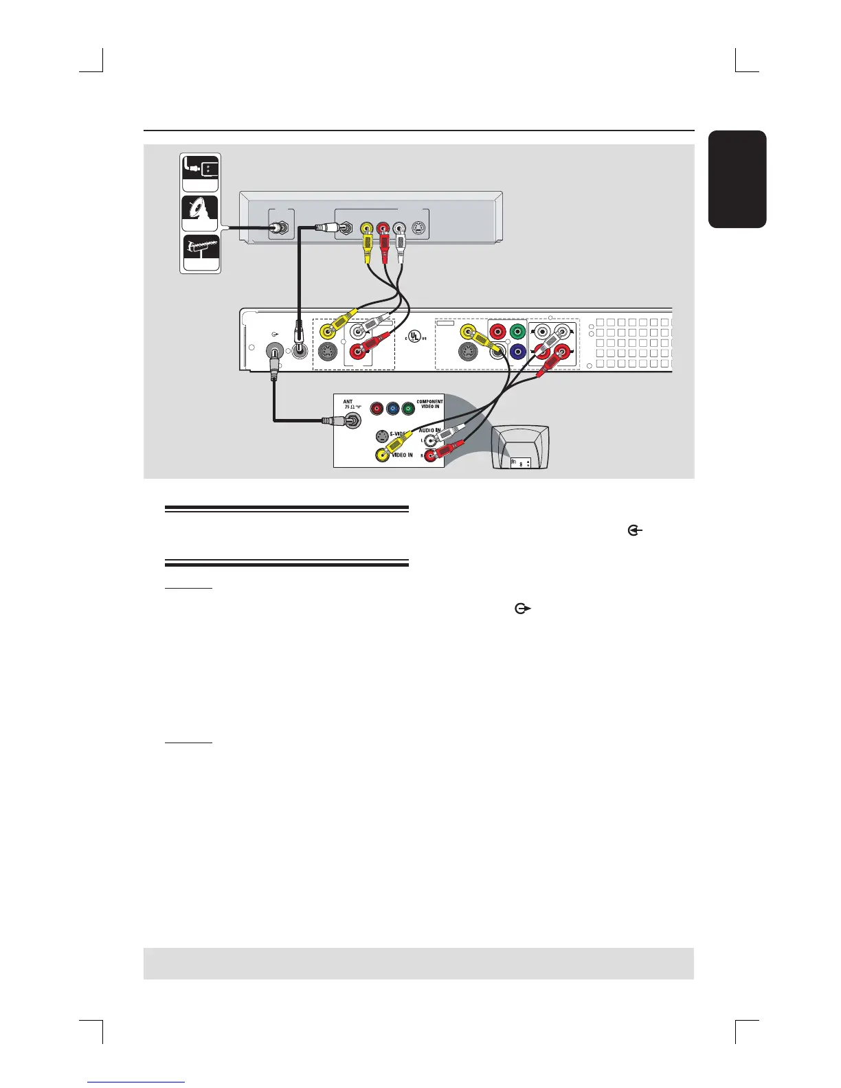
Connecting to a Cable Box or
Satellite Receiver
Option 1
If your Cable Box/Satellite Receiver
has only an antenna output jack
(RF OUT or TO TV),
see the chapter “Step 1: Basic Recorder
Connections – Connecting the antenna
cables” for the complete connection
to your TV.
Option 2
If your Cable Box/Satellite Receiver
has video/audio output jacks,
A
Keep the existing connection from the
Antenna/TV Cable Signal to the antenna
input (RF-IN) jack on the Cable Box/
Satellite Receiver.
B
Use the supplied RF coaxial cable to
connect the ANTENNA-IN
jack on
the recorder to the RF OUT jack on the
Cable Box/Satellite Receiver.
C
Use a RF coaxial cable to connect the
TV-OUT jack on the recorder to
the antenna input jack on your TV (VHF/
UHF RF IN.)
D
Use the audio/video cables to connect
the VIDEO/AUDIO INPUT on the
recorder to the matching VIDEO/AUDIO
output jacks on the Cable Box/Satellite
Receiver.
E
Use the audio/video cables to connect
the VIDEO/AUDIO OUTPUT on the
recorder to the matching VIDEO/AUDIO
input jacks on the TV.
TIPS: Before making or changing any connections, make sure that all the devices are disconnected
from the power outlet.
D
E