Page 27 E
VERFLO
TM
SERVICE & TECHNICAL INFORMATION 1039055, VER. 06
EQUIPMENT REQUIRED FOR OPTION 2
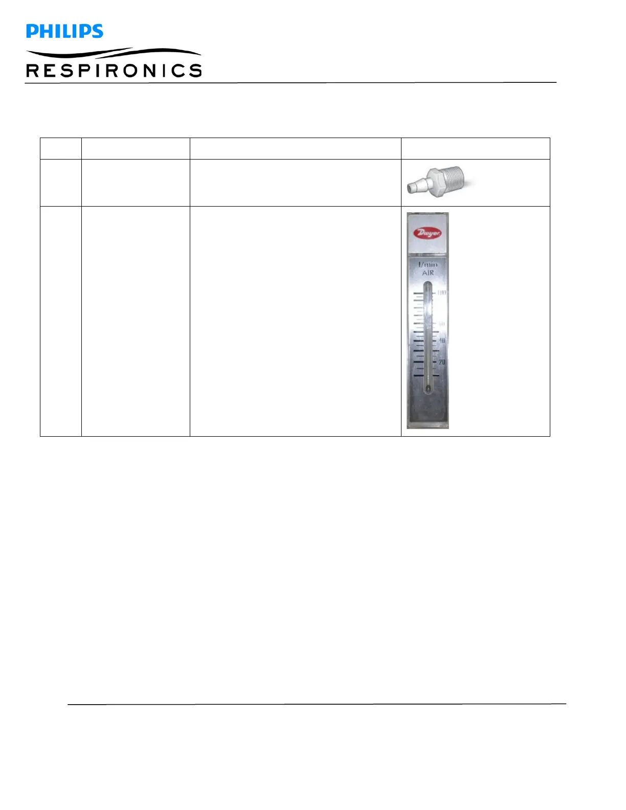
Items 1-4, 6, 9, and 10 as detailed above with the addition of the following items:
Male Tube Adapter 1/8” NPT x 3/8” Barb,
McMaster-Carr: Part # 5372K116
Flow Meter, Dwyer Instruments Part # RMA-
25
ASSEMBLY INSTRUCTIONS FOR EQUIPMENT OPTION 1
1. Connect the compressor blue outlet tube to Barbed Tube Fitting Reducing Tee (#1) and secure with a
hose clamp (#6).
2. Thread the Barbed Tubing Fitting Adapter (#10) to the gauge (#3) using Teflon tape.
3. Connect the Tubing Fitting Adapter (#10) to the Reducing Tee (#1) using the High Pressure Tubing (#4).
4. Install the High Pressure Clear Tubing (#9) to the Reducing Tee (#1) and the Needle Valve (#2) and
secure with hose clamps (#6).
5. Install the High Pressure Clear Tubing (#9) to the Needle Valve (#2) and the Single Barbed Tube Fitting
(#5) and secure with hose clamps (#6).
6. Install the 18” Patient Tubing (#7) to the Single Barbed Tube Fitting (#5) and the TSI Flow Meter (#8).
7. Install the power adapter to the TSI Flow Meter (#8) and plug into a 120 VAC/60 Hz outlet.