Page 28 E
VERFLO
TM
SERVICE & TECHNICAL INFORMATION 1039055, VER. 06
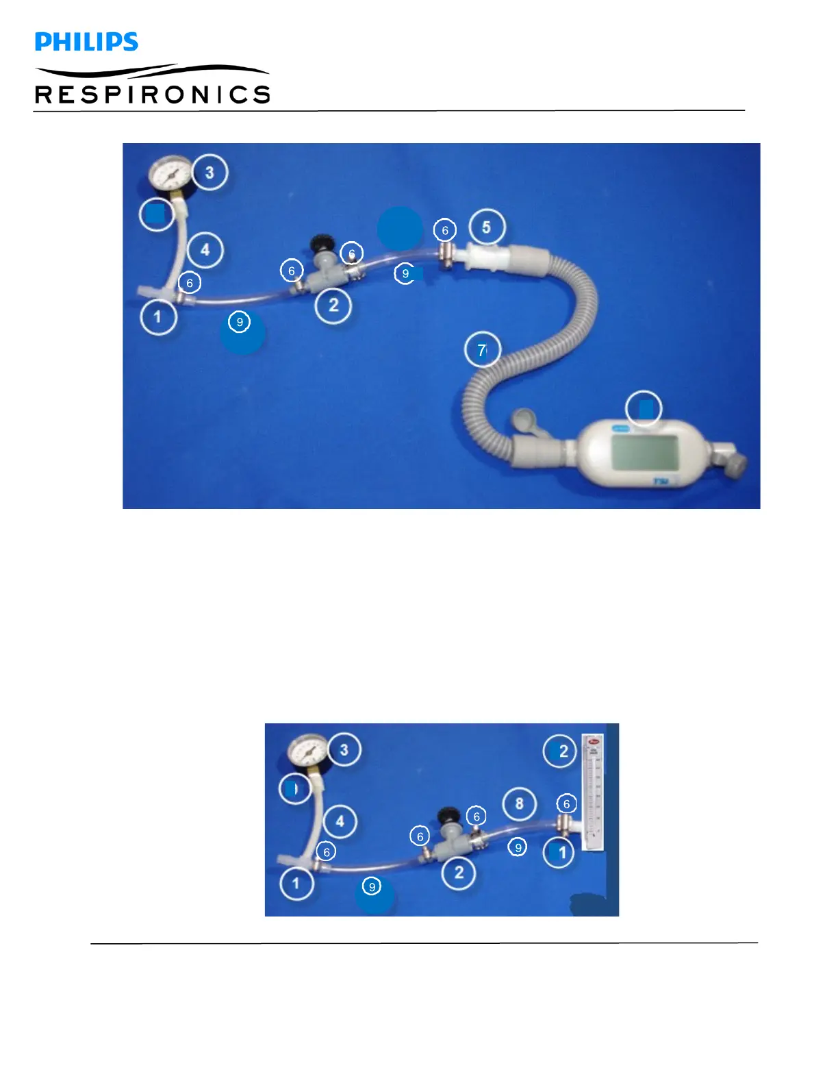
ASSEMBLY INSTRUCTIONS FOR EQUIPMENT OPTION 2
1.
Connect the compressor blue outlet tube to Barbed Tube Fitting Reducing Tee (#1) and secure
with a hose clamp (#6).
2.
Thread the Barbed Tubing Fitting Adapter (#10) to the gauge (3) using Teflon tape.
3.
Connect the Tubing Fitting Adapter (#10) to the Reducing Tee (#1) using the High Pressure Tubing
(#4).
4.
Install the High Pressure Clear Tubing (#9) to the Reducing Tee (#1) and the Needle Valve (#2)
and secure with hose clamps (#6).
5.
Install the High Pressure Clear Tubing (#9) to the Needle Valve (#2)
6.
Install the 1/8” Male Tube Adapter (#12) to the Flow Meter (#13) using Teflon tape.
7.
Install the High Pressure Clear Tubing (#9) to the 3/8” Male Tube Adapter (#12) and secure with
a hose clamp (#6).