Page 56 E
VERFLO
TM
SERVICE & TECHNICAL INFORMATION 1039055, VER. 06
5.
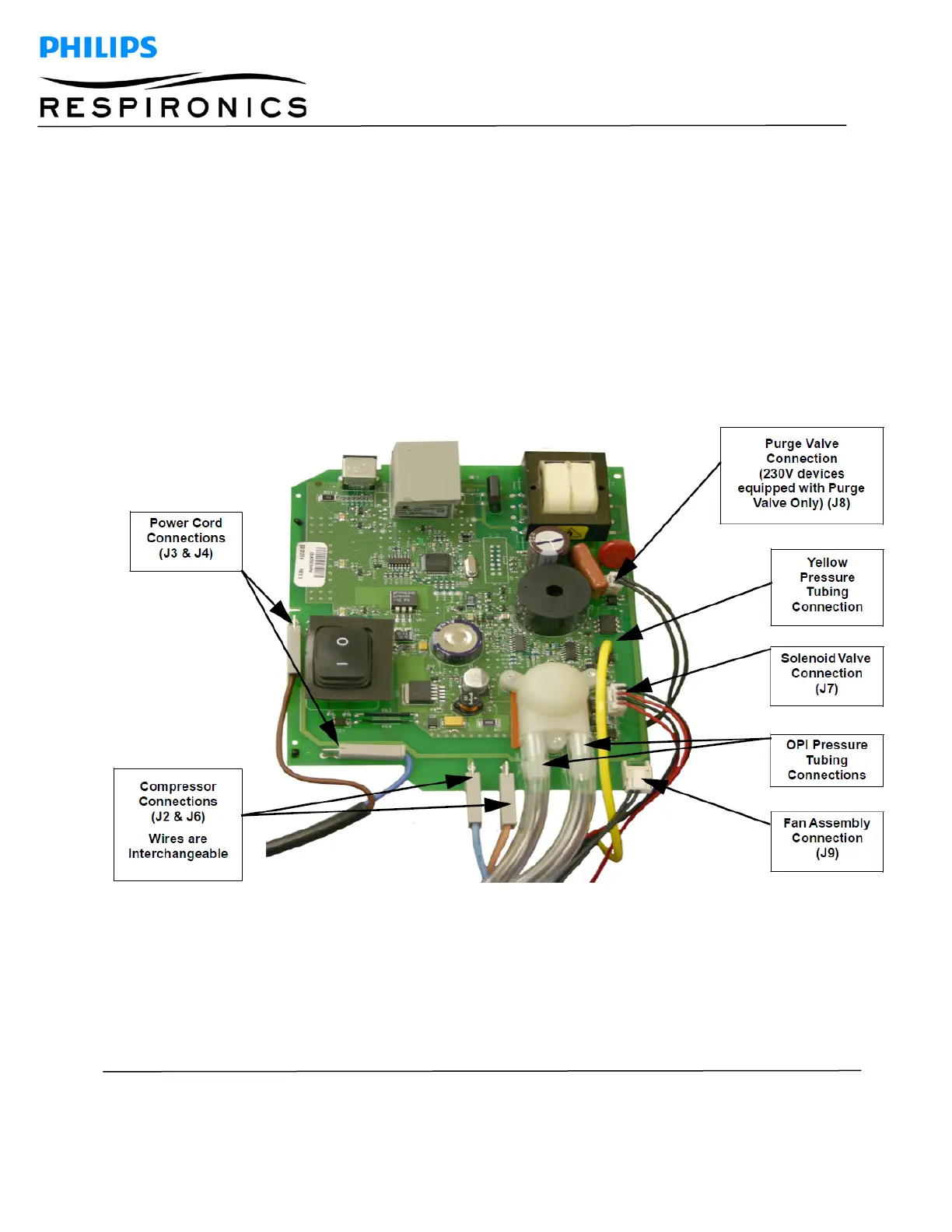
Remove the Power Cord Connectors from the J3 and J4 locations of the Main PCA. Refer to
Figure 8-15.
6.
Remove the Fan Connector from the J9 location of the Main PCA. Refer to Figure 8-15.
7.
Remove the Valve Solenoid Connector from the J7 location of the Main PCA. Refer to Figure 8-
15.
8.
Remove the Purge Valve Connector from the J8 location of the Main PCA (230V devices equipped
with a Purge Valve Only). Refer to Figure 8-15.
9.
Gently remove the yellow pressure line coming from the Pressure Regulator Adaptor from the
pressure sensor (SN1) of the Main PCA. Refer to Figure 8-15.
10.
Remove the two pieces of flow tubing from the OPI sensor on the Main PCA (OPI devices only).
Refer to Figure 8-15.
11.
Slide the Main PCA upward from the grooves in the Front Cabinet.
12.
Remove the Compressor Wires from the J2 and J6 locations of the Main PCA. Refer to Figure 8-
15.
Figure 8-15: CONNECTION POINTS ON THE MAIN PCA