Circuit Descriptions and List of Abbreviations
EN 100 FM249.
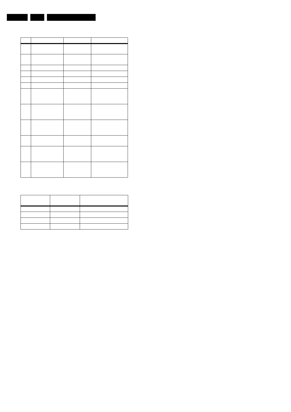
Table 9-3 PixelWorks Scaler: Ports
Table 9-4 PixelWorks Scaler: Video Select
Service remark: Desoldering/soldering of this IC requires very
specialised (BGA) equipment. This can only be done by the
Authorised Service Centres (ASC).
The EPLD
The main reason to add the EPLD is the contrast reserve
function. Other reasons:
• Black and white ADC adjustment. The EPLD provides a
high-resolution measurement of the black and white level,
to adjust the gain and offset of the ADC (AD9887). It is read
via I
2
C.
• LVDS reset. This function resets the LVDS transmitter on
the SCAVIO board, in case the LVDS transmitter starts up
without a clock. This could cause an abnormal picture.
Therefore, as soon as the clock is not fast enough (as
during start-up) the EPLD will keep the LVDS transmitter in
reset.
• Receiver-box mode detection. For loop through mode (a
second FTV monitor connected to the output of the first
monitor), a secondary detection is needed to check the
presence of an Receiver or E-box.
• ATSC sync detection/ decoding. Core for proper sync
decoding for ATSC sources.
• Contrast reserve. This function can increase the gain of
the video signal to a factor of two. It will reduce the gain
again if it sees too many overflows (code 255) in any of the
R, G, or B channels. Adjustable via two parameters: user
contrast and overflow limit. Parameters are I
2
C controlled.
The LVDS transmitter
This DS90C385MTD56 IC from National Semiconductors
converts 28 bits of CMOS/TTL data into four LVDS (Low
Voltage Differential Signalling) data streams. A PLL transmit
clock is transmitted in parallel with the data streams over a fifth
LVDS link. Every cycle of the clock, 28 bits of input data are
sampled and transmitted. At a transmit clock frequency of 36
MHz, 24 bits of RGB data and 3 bits of display control data are
transmitted per LVDS data channel. This IC operates at 3.3 V
For more information, see http://www.national.com/
Picture Mute
In some cases, it is necessary to mute the video output:
• In Monitor mode:
– During switch 'on/off' of the monitor,
– During source change,
– During video or sync loss, or
– By a user action (A/V-mute or mute)
– In audio only mode (when the ICONN-box is
connected).
• In TV mode:
– During switch 'on/off' of the Monitor/Receiver box,
– During source change in the Receiver box,
– During video or sync loss, or
– In audio only mode (Receiver box mutes the picture).
Most of the picture mute controls are done via the PixelWorks
co-processor.
Anti Ageing
In order to prevent visible luminance differences, due to ageing
of the monitor, a special algorithm is implemented. This
algorithm is based on horizontal shifting of the picture in the
monitor. For good understanding some terms will now first be
explained:
• Ageing: The effect that the efficiency of a plasma cell
(pixel) decreases as a function of the total time that it is
illuminated. This effect occurs mostly because of phosphor
ageing. As a result, the cell brightness decreases over
time. An alternative name for ageing is 'burn-in'.
• Picture shifting: Fixed structures, like logo's, OSDs, and
subtitles, will cause burn-in effects. The only way to mask
this to a certain extends, is picture shifting so that the 'burn-
in' effect is smeared out over a larger area, and makes it
less visible.
Most of the anti-ageing controls are implemented in the
PixelWorks co-processor.
Horizontal
Horizontal anti-ageing steps:
• Step width/height, the step width/height shall be 1
horizontal pixel width (approx. 1 mm).
• Number of steps, the maximum number of steps in
horizontal direction shall be 9.
• Time between steps, the time between the steps shall be
5 minutes.
The effect of H anti-ageing is a horizontal movement
(start at 0):
0 → 1 → 2 → 3 → 4
12 ← 11← 10 ← 9 ← 8 ← 7 ← 6 ← 5 ←
→ 13→ 14 → 15
With the following sequence:
0 → 1 → 2 → ...... → 14 → 15 → 0 → 1 → etc.
After every step, the updated value is stored in NVM and gives
an indication about the direction (0...4 and 13...15 to the right
and 5...12 to the left).
The horizontal anti-ageing is a process, which is basically
independent of any other processes that are running in SW.
This means that this process should never be reset in order to
get the best anti-ageing effect. Therefore, the horizontal shift
positions and directions need to be stored in NVM, so that he
anti-ageing process returns to its latest position after the set
has been switched off or to standby. There is only one H and
Pin Name I/O Remark
C2 PW_SCL +3V3 output to I2C devices, Vid-
eo related
B1 PW_SDA +3V3 output to I2C devices, Vid-
eo related
A1 PW_SDA_NVM +3V3 output to I2C device NVM
C4 PW_SCL_NVM +3V3 output to I2C device NVM
B3 SCL_2 +3V3 output to I2C device OTC
A2 SDA_2 +3V3 output to I2C device OTC
A3 VIDEO_SEL_1 +3V3 output to video selection
switches (see truth
table)
C5 VIDEO_SEL_2 +3V3 output to video selection
switches (see truth
table)
B4 VGA2_OUTN +3V3 output Selects VGA 2 as
output. (Low =>
Output)
A4 VGA2_EN +3V3 output Enables VGA 2
(High = Enable)
C6 SYNC Input Is 'high' if EPLD de-
tects separate sync
signals on YPbPr
B5 1_2FH Input Is 'high' if sync on
YPbPr is 1fH (from
EPLD)
VIDEO_SEL_1 VIDEO_SEL_2 Selected input for
AD9887
00 RGB 2fh
0 1 YPbPr 2fh
10 VGA 1
11 VGA 2
www.freeservicemanuals.info
Digitized in Heiloo, Holland