EN 8
3139 785 318712.
Measurements Setup, Service Aid & Lead Free Requirements
2.2 Service Hints
CAUTION
CHARGED CAPACITORS ON THE SERVO BOARD MAY DAMAGE THE DRIVE
ELECTRONICS WHEN CONNECTING A NEW DRIVE.THAT’S WHY, BESIDES THE SAFETY
MEASURES LIKE
• SWITCH OFF POWER SUPPLY
• ESD PROTECTION
ADDITIONAL ACTIONS MUST BE TAKEN BY THE REPAIR TECHNICIAN.
The following steps have to be done when replacing the defective loader :
1. Dismantling of the loader to access the ESD protection point if necessary.
2. Solder the ESD protection point*.
3. Disconnect fl exfoil cable from the defective loader.
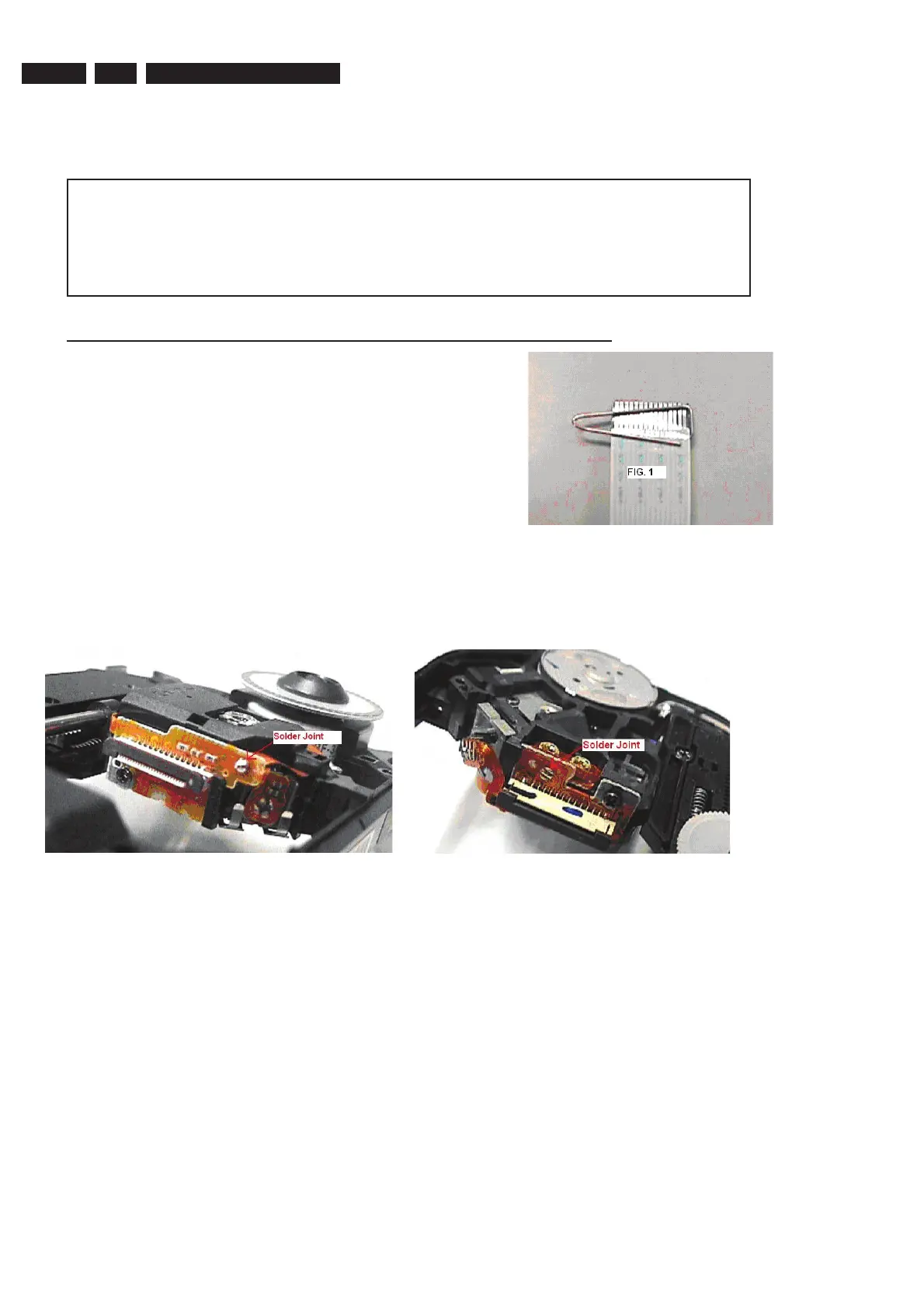
4. Put a paper clip on the fl exfoil to short-circuit the contacts (fi g.1)
5. Replace the defective loader with a new loader.
6. Remove paperclip from the fl exfoil and connect it to the new loader.
7. Remove solder joint on the ESD protection point.
ATTENTION: The laser diode of this loader is protected against ESD by a solder joint which shortcircuits the laserdiode to ground.
For proper functionality of the loader this solder joint must be remove after connection loader to the set.
Type 1 Type 2
(ESD protection point is accessible from top of loader) (ESD protection point is accessible from bottom of the loader)
*Only applicable for defective loader needed to be sent back to supplier for failure analysis and to support backcharging
evidence.
This is also applicable for all partnership workshops.
 Loading...