3-3
Mechanical and Dismantling Instructions
Dismantling Instruction
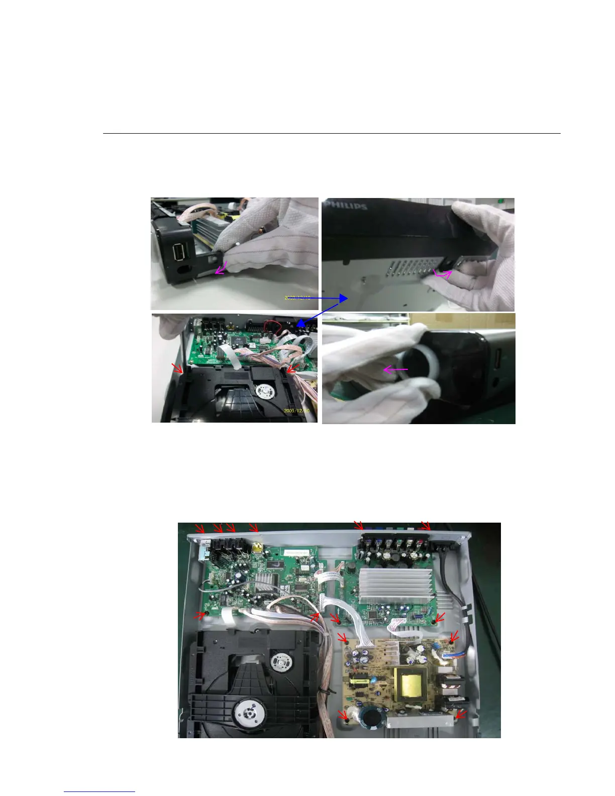
Figure 5
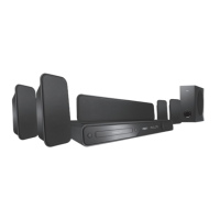
Figure 6
Detailed information please refer to the model set.
Step6: Dismantling Main Board, first disconnect 3 connectors (XP1, XP10, XP11), and then remove 6 screws. (Figure 6)
Step7: Dismantling Power Board, disconnect the connectors XS703 and CON501 then remove 4 screws. (Figure 6)
Step5: Dismantling Loader, disconnect the 3 connectors (XP12, XP13, XP14) aiming in the below figure, and remove 2 screws
that connects the loader and the bottom cabinet. (Figure 5)
Dismantling the Turn Knob assembly, pls refer to below instruction, or poke it out at rearward by forceps. (The last steps of Figure 5)
Step8: Dismantling Amplifier Board, remove 4 screws from the PCB. (Figure 6)